Vertical shaft wind driven generator and distributed energy storage station device

A wind turbine and vertical shaft technology, which is applied to wind turbines and devices that convert solar radiation into useful energy, wind turbines, and wind turbine combinations, etc., can solve the problems of large influence of wind direction and low fan efficiency, and improve power generation efficiency. , the effect of improving rotor rotation efficiency, enhancing layout breadth and practicability

Pending Publication Date: 2021-08-31
莫一凡
View PDF0 Cites 0 Cited by
  • Summary
  • Abstract
  • Description
  • Claims
  • Application Information

AI Technical Summary

Problems solved by technology

[0004] Based on this, the present invention provides and designs a resistance-type vertical-axis wind power generator and distributed energy storage station device to address technical defects such as low efficiency of traditional wind turbines and greater influence by wind direction, while ensuring the simplicity of the product structure and avoiding Technical features of maintenance

Method used


Image

  • Vertical shaft wind driven generator and distributed energy storage station device
  • Vertical shaft wind driven generator and distributed energy storage station device
  • Vertical shaft wind driven generator and distributed energy storage station device

Examples


Embodiment 1

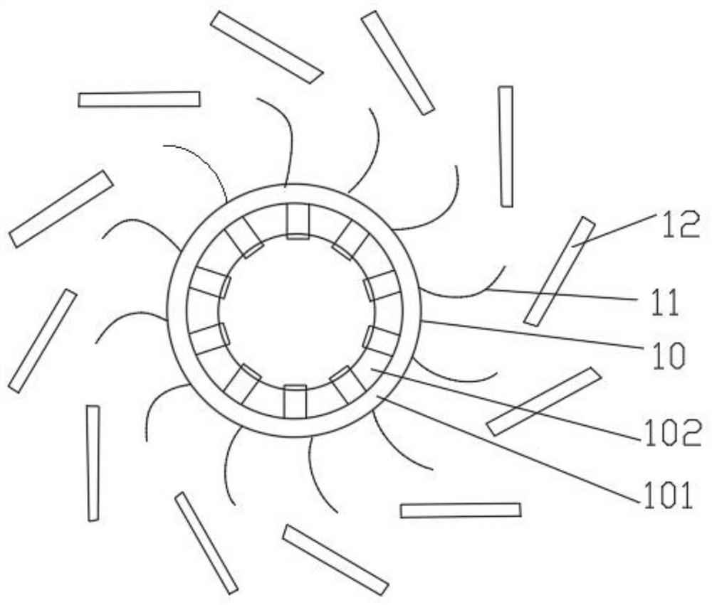
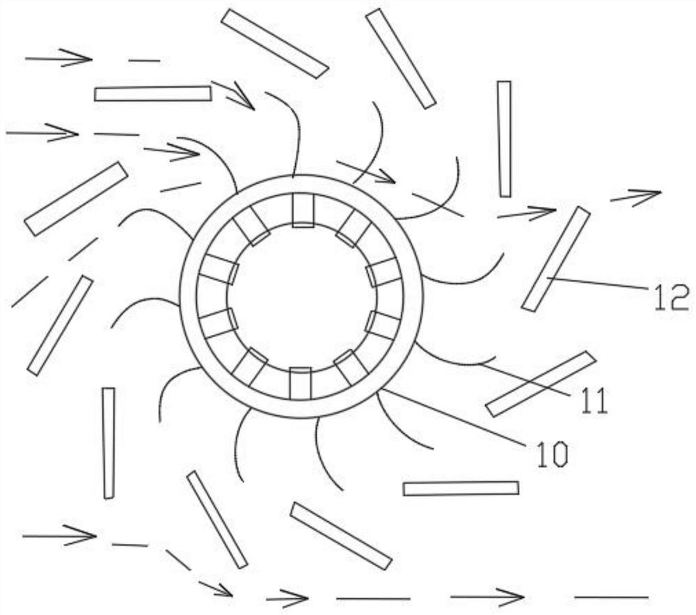
[0032] Please refer to Figure 2-4 , the first embodiment provides a vertical shaft wind power generator 1, including an outer rotor motor device 10, blades 11 arranged at intervals along the circumferential direction on the outer wall surface of the outer rotor motor device 10; and along the blades 11 The deflector 12 arranged on the periphery of the

[0033] Wherein, the number of the deflectors 12 is consistent with the number of the blades 11, and each deflector 12 is set in one-to-one correspondence with the corresponding blades 11; Conditions and cost considerations N=3, 4, 5, 6, 8, 9, 10, 12, it is not necessary that the number of vanes and deflectors be equal.

[0034] The cross-section of the blade 11 is a concave curved surface (the cross-section of the blade is a curved surface, and it is the concave surface of the above-mentioned curved surface that is propelled by the wind), and a plurality of the deflectors 12 are distributed with an inclination angle around the...

Embodiment 2

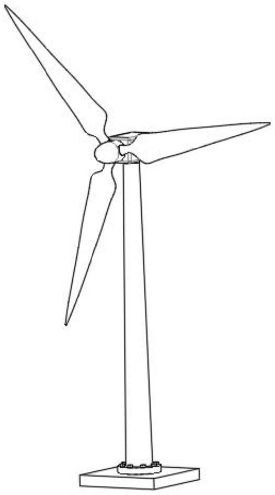
[0055] Please refer to Figure 6-Figure 8 , this embodiment 2 provides a distributed energy storage station device, including the vertical axis wind power generator 1 provided in the above embodiment 1, the support body 2 arranged at the bottom of the vertical axis wind power generator and the The energy storage base 3 at the bottom and the energy storage photovoltaic interface; the inside of the energy storage base 3 is provided with an energy storage system 4; the vertical axis wind generator is electrically connected to the energy storage system through wire lines; the photovoltaic panel It is electrically connected with the energy storage system 4 through wires; the energy storage system 4 includes multiple storage battery packs and other structures, which will not be repeated here.

[0056] The second embodiment provides a distributed energy storage station device, which installs the energy storage system 4 inside the energy storage base 3. The airtight anti-theft functi...


PUM


Abstract

The invention relates to a vertical shaft wind driven generator and a distributed energy storage station device. The vertical shaft wind driven generator comprises an outer rotor motor device, blades arranged on the surface of the outer wall of the outer rotor motor device at intervals in the circumferential direction, and flow guide plates arranged along the peripheries of the blades; The guide plates are arranged along the peripheries of the blades; the cross section of each blade is an inwardly concave curved surface, the multiple flow guide plates are distributed on the peripheries of the blades by taking the outer rotor motor device as a center inclined angle, the flow guide plates are linear base plates, and the included angle between every two adjacent flow guide plates is 360 / N (N is equal to the number of the flow guide plates). According to the vertical shaft wind driven generator and the distributed energy storage station device, the rotation efficiency of a rotor in the vertical shaft wind driven generator is guaranteed, and finally the wind power generation effect is remarkably improved.

Description

technical field [0001] The invention relates to the technical field of wind power generation equipment, in particular to a vertical shaft wind power generator and a distributed energy storage station device. Background technique [0002] With the continuous development of clean energy, more and more electric power companies have begun to devote themselves to the research of wind power generation. In wind power generation, wind turbines are commonly used equipment, and blades are indispensable accessories for wind power generators. [0003] see figure 1 , the blades in the commonly used technology are conventional long strip blades, the short is three to five meters, and the length is more than ten meters or tens of meters. Low efficiency, high low-frequency noise, need to face the wind, need a gear speed increaser, easy to collide with flying objects such as birds, etc. It is important to note that the blades of the traditional lift-type three-blade wind turbine are directl...

Claims


Application Information

Patent Timeline
Patent Type & Authority Applications(China)
IPC IPC(8): F03D9/25F03D3/00F03D3/06F03D3/04F03D13/20F03D9/11H02S10/12
CPCF03D9/25F03D3/005F03D3/061F03D3/0418F03D13/20F03D9/11F03D9/007H02S10/12F05B2240/301F03D3/062Y02E70/30Y02E10/74Y02E10/728Y02E10/50
Inventor 莫一凡
Owner 莫一凡
Why Eureka
Try Eureka