
Silent negative pressure circulation oxygen generator

An oxygen generator and negative pressure technology, applied in the field of oxygen generators, can solve the problems of complicated molecular sieve replacement, poor air circulation effect, low air replacement rate, etc., to avoid bad experience and low-frequency noise damage, convenient maintenance, and simplified disassembly. The effect of the installation steps

Active Publication Date: 2021-08-31
永康市优哈电器有限公司
View PDF6 Cites 0 Cited by
  • Summary
  • Abstract
  • Description
  • Claims
  • Application Information

AI Technical Summary

Problems solved by technology

Molecular sieves are filled in the oxygen concentrator, which can absorb nitrogen in the air when pressurized, and the remaining unabsorbed oxygen is collected, which becomes high-purity oxygen after purification treatment. Nitrogen is discharged back into the ambient air, and it can absorb nitrogen and produce oxygen during the next pressurization. The whole process is a periodic dynamic cycle process, and molecular sieves are not consumed. The existing molecular sieves are zeolite molecular sieves. The existing household oxygen production The air compressor is used as the pressure source by the air compressor, and the noise has a great impact on the patient, and the air replacement rate is low in the process of decompression relying on its nitrogen molecules to separate from the molecular sieve, which makes the air circulation effect poor. The oxygen rate is low, which will cause the acceleration of the air compressor to waste energy and increase the noise, and the replacement of the molecular sieve is extremely cumbersome. Therefore, it is necessary to use a negative pressure to accelerate the internal pressure of the molecular sieve while decompressing the molecular sieve. Air exchange improves oxygen production efficiency, and ordinary people can quickly replace molecular sieve devices without tools

Method used


Image

  • Silent negative pressure circulation oxygen generator
  • Silent negative pressure circulation oxygen generator
  • Silent negative pressure circulation oxygen generator

Examples


Embodiment Construction

[0030] The present invention will be described in detail below in conjunction with the accompanying drawings.

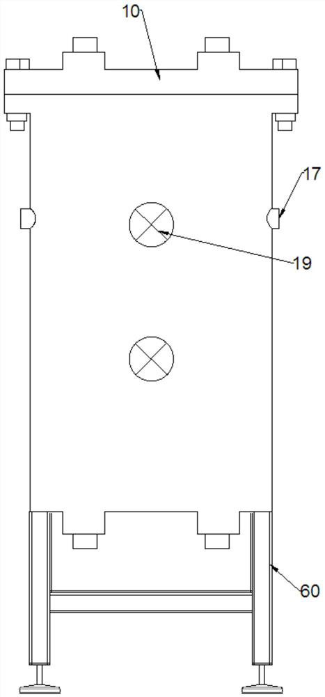
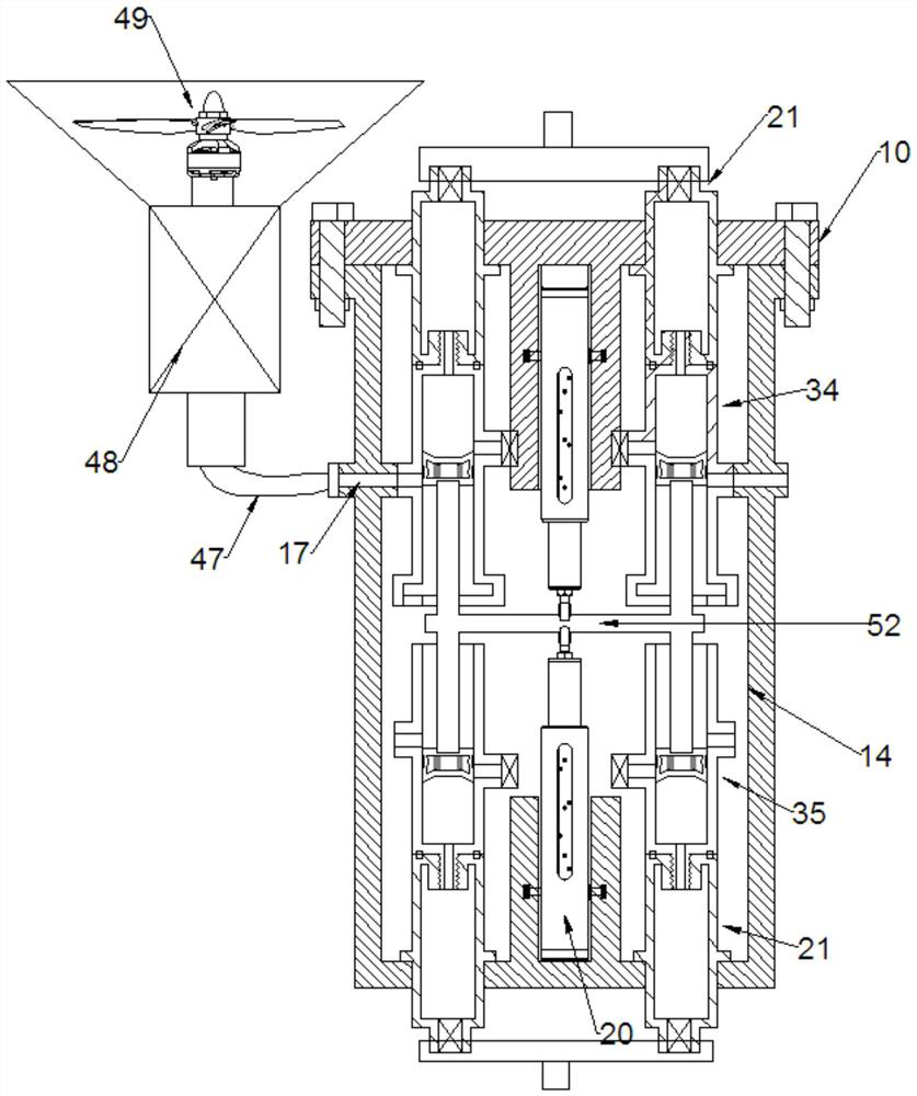
[0031] A silent negative pressure circulation oxygen generator described in conjunction with accompanying drawings 1-6 includes an end cover 10 and a housing 14. The end cover 10 is a round cake-shaped flange, and the left and right symmetrical arrangements are made on the end cover 10. There are two molecular sieve positioning holes 12 penetrating up and down, the inner wall of the lower end of the end cover 10 is fixed with a positioning flange 11, the upper end of the housing 14 is provided with an opening, and the inside of the housing 14 is provided with a cavity 18. The middle part of the housing 14 is symmetrically provided with two air inlet joints 17 penetrating left and right, and the lower end of the housing 14 is symmetrically provided with two molecular sieve holes 15 penetrating up and down. Clamp block 16, the middle part of the housing 14 is provided ...


PUM


Abstract

The invention relates to the field of oxygen generators, and discloses a silent negative pressure circulation oxygen generator, which comprises an end cover and a shell, two vertically through molecular sieve positioning holes are bilaterally symmetrically formed in the end cover, a positioning flange is fixedly arranged on the inner wall of the lower end of the end cover, an opening is formed in the upper end of the shell, and a cavity is formed in the shell. Two air inlet joints penetrating left and right are arranged in the middle of the shell in a bilateral symmetry mode, and two molecular sieve holes penetrating up and down are formed in the lower end of the shell in a bilateral symmetry mode. The device has the beneficial effects that the special combination of a molecular sieve column and a main piston cylinder is adopted, and the compression of a special piston is used for replacing the compression of an air compressor, so that the equipment cost is greatly reduced, the equipment structure is simpler, meanwhile, no noise is generated in the working process, and bad experience and low-frequency noise damage to a user are avoided.

Description

technical field [0001] The invention relates to the field of oxygen generators, in particular to a silent negative pressure circulation oxygen generator. Background technique [0002] Existing small oxygen generators use molecular sieve physical adsorption and desorption technology. Molecular sieves are filled in the oxygen concentrator, which can absorb nitrogen in the air when pressurized, and the remaining unabsorbed oxygen is collected, which becomes high-purity oxygen after purification treatment. Nitrogen is discharged back into the ambient air, and it can absorb nitrogen and produce oxygen during the next pressurization. The whole process is a periodic dynamic cycle process, and molecular sieves are not consumed. The existing molecular sieves are zeolite molecular sieves. The existing household oxygen production The air compressor is used as the pressure source by the air compressor, and the noise has a great impact on the patient, and the air replacement rate is low...

Claims


Application Information

Patent Timeline
Patent Type & Authority Applications(China)
IPC IPC(8): C01B13/02B01D53/04B01D46/00
CPCC01B13/0259B01D53/04B01D53/0407B01D46/00C01B2210/0018
Inventor 李欢
Owner 永康市优哈电器有限公司
Learn More