


Quick Research
Generate reliable direction feasibility study reports for your R&D in just a few steps.

Technical Q&A
Discover and master advanced knowledge NOW. Basics, ideas, possibilities, all at once.

Find Solutions
As an expert in R&D theories, this can generate solutions to your technical problems instantly.

Evaluate Feasibility
Analyze your overall solution with one click, know your potential R&D risks in advance.

Monitor Landscape
Get weekly tech updates, stay abreast of the latest tech innovations and key insights.
PWM dimming control type TLCC drive circuit
A dimming control and drive circuit technology, applied in the field of drive circuits, PWM dimming control type TLCC drive circuits, can solve problems such as flicker, achieve outstanding performance, alleviate the problem of lack of chips, and achieve the effect of over-temperature automatic protection
- Summary
- Abstract
- Description
- Claims
- Application Information
AI Technical Summary
Problems solved by technology
Method used
Image

Examples
Embodiment 1
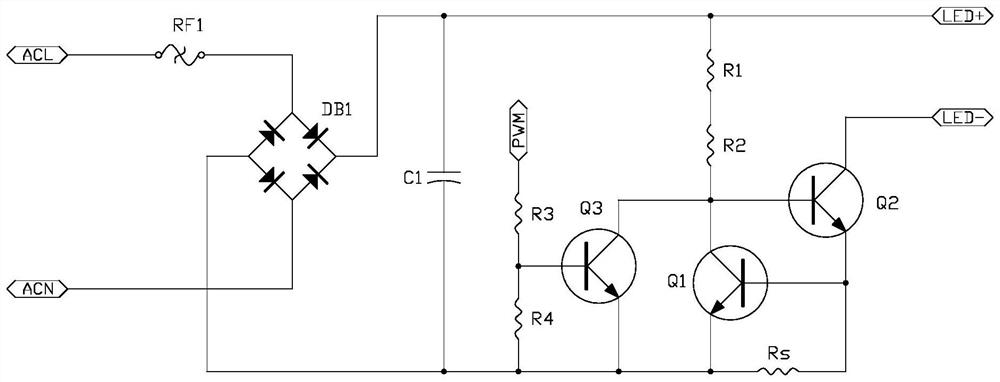
[0027] refer to figure 1 , a PWM dimming control type TLCC drive circuit of the present invention, comprising a power supply, a dimming module, an over-temperature protection module and an LED load, the dimming module is arranged between the power supply and the over-temperature protection module, the dimming The optical module includes a triode Q3, a current limiting resistor R3, a grounding resistor R4 and a pulse width modulator PWM, the base of the triode Q3 is connected to the communication interface of the pulse width modulator PWM through the current limiting resistor R3 The resistor R4 is connected to the cathode loop end of the power supply, and the emitter of the triode Q3 is connected to the cathode loop end of the power supply;
[0028] The pulse width modulator PWM switches the PWM signal to a floating or low-level state, and uses the transistor Q3 to turn on the over-temperature protection module, so that the LED load and the power supply are conducted;
[0029]...
Embodiment 2
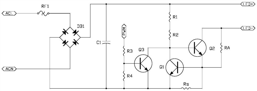
[0049] refer to figure 2 , a shunt resistor is connected between the collector of the triode Q2 and the emitter of the triode Q2.
[0050] Others are the same as embodiment one.
[0051] The shunt resistor RA added in parallel between the collector of the transistor Q2 and the emitter of the transistor Q2 in the TLCC drive circuit has a unique function of shunting and dividing power consumption, which can make the positive terminal of the LED load flow into the negative terminal of the LED load. The circuit is divided into two paths. One of the two currents directly flows through the collector of the transistor Q2 to the emitter of the transistor Q2 , while the other current flows through the shunt resistor RA and then flows to the emitter of the transistor Q2 . The two currents are finally brought together at the emitter of the transistor Q2, and then connected to the base of the transistor Q1 to form a loop to the ground through the constant current resistor Rs.
[0052]...
Embodiment 3
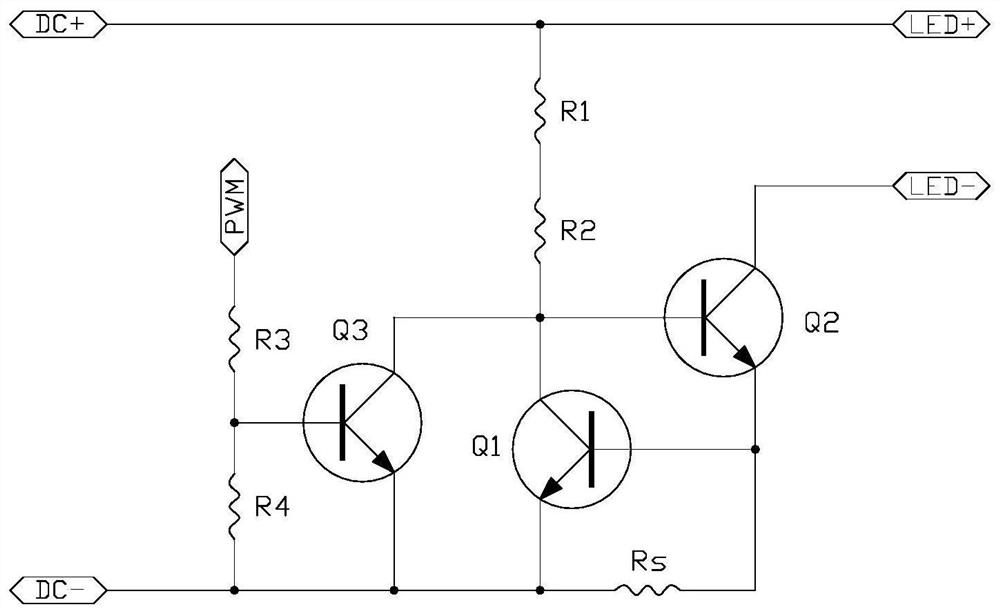
[0054] refer to image 3 , a PWM dimming control type TLCC drive circuit of the present invention, comprising a power supply, a dimming module, an over-temperature protection module and an LED load, the dimming module is arranged between the power supply and the over-temperature protection module, the dimming The optical module includes a triode Q3, a current limiting resistor R3, a grounding resistor R4 and a pulse width modulator PWM, the base of the triode Q3 is connected to the communication interface of the pulse width modulator PWM through the current limiting resistor R3 The resistor R4 is connected to the cathode loop end of the power supply, and the emitter of the triode Q3 is connected to the cathode loop end of the power supply;
[0055] The pulse width modulator PWM switches the PWM signal to a floating or low-level state, and uses the transistor Q3 to turn on the over-temperature protection module, so that the LED load and the power supply are conducted;
[0056]...
PUM
 Abstract
Description
Claims
Application Information
 - R&D Engineer
- R&D Manager
- IP Professional
- Industry Leading Data Capabilities
- Powerful AI technology
- Patent DNA Extraction
Browse by: Latest US Patents, China's latest patents, Technical Efficacy Thesaurus, Application Domain, Technology Topic, Popular Technical Reports.
© 2024 PatSnap. All rights reserved.Legal|Privacy policy|Modern Slavery Act Transparency Statement|Sitemap|About US| Contact US: help@patsnap.com