
Satellite gravity field inversion method

A gravity field and inversion technology, applied in the field of geophysical exploration, can solve the problems of poor resolution of the inversion density model, slow convergence speed, large memory usage of the forward and inversion kernel matrix, etc., to speed up implementation and reduce memory The effect of occupying and improving the reusability

Active Publication Date: 2021-08-27
CENT SOUTH UNIV
View PDF6 Cites 7 Cited by
  • Summary
  • Abstract
  • Description
  • Claims
  • Application Information

AI Technical Summary

Problems solved by technology

[0006] The longitude-latitude coordinate axis of the traditional tesseroid unit has "warping", which makes the process of calculating the smoothness coefficient of the roughness matrix more complicated, the constraint ability of the inversion model fitting item is low, and the convergence speed is slow, so the inversion result cannot be guaranteed Resolution in its horizontal and depth directions
[0007] Based on the above description, there is an urgent need for a new satellite gravity field inversion method to solve the problems in the existing technology that it is difficult to use tesseroid grids to achieve global physical property inversion, the forward and inversion kernel matrix takes up a lot of memory, and the inversion density model is in Poor resolution in direction and λ direction, slow inversion speed, inability to ensure horizontal and depth resolution of inversion results, difficulty in effectively realizing multi-component joint inversion and low inversion accuracy

Method used


Image

  • Satellite gravity field inversion method
  • Satellite gravity field inversion method
  • Satellite gravity field inversion method

Examples


Embodiment Construction

[0053] In order to better understand the method and steps of the present invention, the satellite gravity field inversion method of the present invention will be further described in detail below in conjunction with the accompanying drawings.

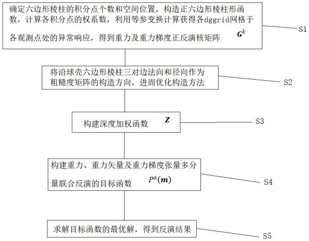
[0054] Such as figure 1 As shown in the flow process, the satellite gravity field inversion method of the present invention is based on isoparametric transformation of the global discrete network, and the specific steps are as follows:

[0055] Determine the thickness H of the spherical shell in the research area, and divide it into n equally along the radial direction of the spherical shell z Layer, according to the definition of the global discrete grid, construct the first-level grid on the spherical surface (the nth-level grid can also be further constructed on the spherical surface), of which there are 12 pentagonal global discrete grids, and six-sided 30 global discrete grids, and use these grids on the spherical surface to discr...


PUM


Abstract

The invention discloses a satellite gravity field inversion method. The method comprises the following steps of: obtaining gravity, gravity vector and gravity gradient tensor data and a corresponding kernel matrix through isoparametric transformation; generating a corresponding depth weighting matrix; constructing a target function of multi-component joint inversion; and finally obtaining an inversion result. Compared with a traditional spherical shell unit, the dggrid used in the method can improve the reuse capability of a kernel function and reduce the memory occupation of a kernel matrix. Meanwhile, the characteristic that the dggrid has consistent adjacency is utilized, and center lines on three opposite sides of the dggrid serve as the roughness matrix construction direction, so that the purposes of optimizing the construction of a roughness matrix and simplifying the calculation of the smoothness coefficient of the roughness matrix are achieved. Besides, in the inversion optimization solution process, by using a depth weighting matrix irrelevant to the component attenuation characteristic, the multi-gravity / gravity vector / gravity gradient tensor component joint inversion setting is optimized, the convergence speed is accelerated, and the inversion accuracy is improved.

Description

technical field [0001] The invention belongs to the technical field of geophysical exploration, and in particular relates to a satellite gravity field inversion method based on isoparametric transformation of global discrete grid spherical coordinates. Background technique [0002] In the spherical coordinate system, the physical property inversion along the latitude The three directions of longitude λ and radial direction r are divided into unit blocks at equal intervals, and such units are called Tesseroid unit bodies of longitude and latitude grids. The biggest advantage of the latitude-longitude grid is that the grid encoding process is simple, and the transformation with three-dimensional space coordinates is easy to implement. However, as the latitude increases, the longitude-latitude grid will degenerate from the equator to the poles in the spherical coordinate system, and the quadrilateral will degenerate into a triangle near the poles, resulting in a large amount ...

Claims


Application Information

Patent Timeline
Patent Type & Authority Applications(China)
IPC IPC(8): G01V7/00
CPCG01V7/00
Inventor 鲁光银张东兴朱自强张亮毛雅静郭晓旺曹书锦许刚马致远
Owner CENT SOUTH UNIV
Learn More