Fluid control valve with multi-stage monitoring function

A fluid control valve and functional technology, applied in the field of control valves, can solve the problems of no monitoring function, easy wear, and inability to grasp the change of the flow rate of liquid flowing through the control valve, etc., and achieve the effect of quick and convenient replacement

Pending Publication Date: 2021-08-24
肖咸伟
View PDF7 Cites 0 Cited by
  • Summary
  • Abstract
  • Description
  • Claims
  • Application Information

AI Technical Summary

Problems solved by technology

Although some control valves have wider application conditions than others, control valves cannot be used in all conditions to jointly build the best solution to enhance performance and reduce costs
[0003] The spool of a general fluid control valve needs to be rotated frequently, so it is easy to wear. At the same time, the general fluid control valve is manually adjusted and does not have a monitoring function, so it is impossible to grasp the change of the flow rate of the liquid before and after the control valve. Therefore, Propose a fluid control valve with multi-stage monitoring function

Method used


Image

  • Fluid control valve with multi-stage monitoring function
  • Fluid control valve with multi-stage monitoring function
  • Fluid control valve with multi-stage monitoring function

Examples


Embodiment Construction

[0038] The following will clearly and completely describe the technical solutions in the embodiments of the present invention with reference to the accompanying drawings in the embodiments of the present invention. Obviously, the described embodiments are only some, not all, embodiments of the present invention. Based on the embodiments of the present invention, all other embodiments obtained by persons of ordinary skill in the art without making creative efforts belong to the protection scope of the present invention.

[0039] see Figure 1-Figure 6 , the present invention provides a technical solution:

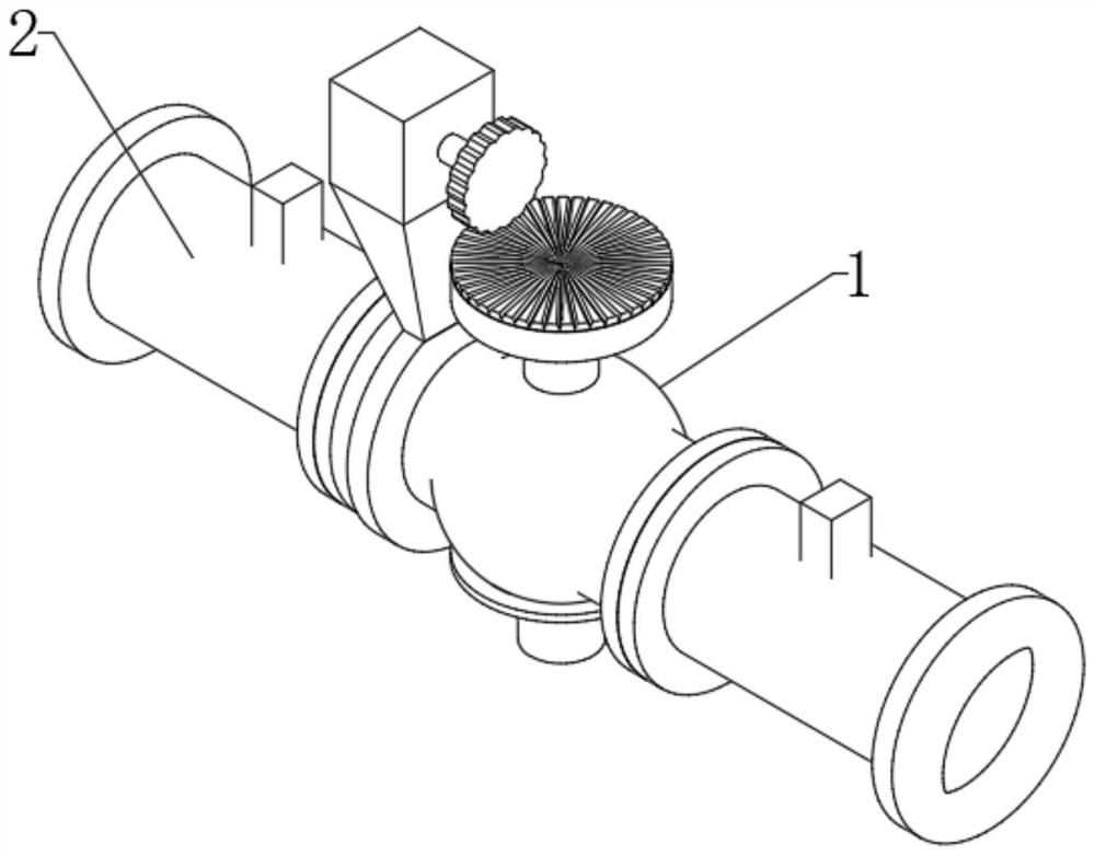
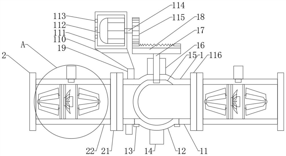
[0040] A fluid control valve with a multi-stage monitoring function, comprising: a valve assembly 1 and a hierarchical monitoring assembly 2 installed on the valve assembly 1;

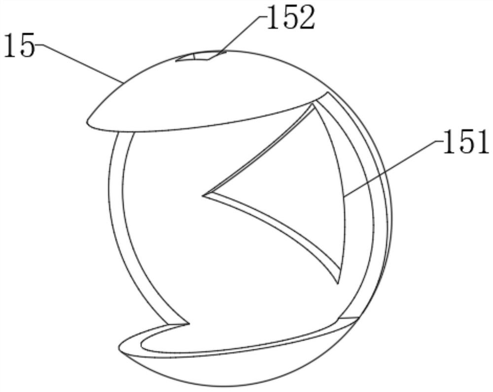
[0041] In order to control the flow rate of the liquid, a valve assembly 1 is provided, wherein the valve assembly 1 includes a valve tube 11, a dial 12, a knob 14, a valve core 15, a valve stem 17,...


PUM


Abstract

The invention discloses a fluid control valve with the multi-stage monitoring function. The fluid control valve comprises a valve assembly and a staged monitoring assembly installed on the valve assembly. According to the fluid control valve, a rotary disc on the valve assembly can be detached in a rotating mode, a valve element is connected to a valve rod in a sliding mode, so that the valve element can be directly detached and replaced after the rotary disc is detached, and replacement is rapid, fast and convenient; a motor drives a rotating shaft to rotate and drives a driving gear to rotate, so that a driven gear is driven to rotate, the valve element is driven to rotate, the position of a valve hole is adjusted, and therefore the cross sectional area where water flow in a valve pipe can pass is adjusted, the flow rate is adjusted, and mechanical adjustment is realized; and when the water flow passes through two pipe bodies, spiral blades are driven to rotate, then a rotating core is driven to rotate, the rotating speed of the rotating core is sensed through a rotating speed sensor, the flowing speed of the water flow is calculated, the rotating speed sensor is electrically connected to a PLC, rotating speed data and flowing speed data are transmitted to an LED display screen through the PLC, and the water flow rate on the two sides of the valve assembly is monitored.

Description

technical field [0001] The invention relates to the technical field of control valves, in particular to a fluid control valve with a multi-stage monitoring function. Background technique [0002] The control valve consists of two main assemblies: the valve body assembly and the actuator assembly (or actuator system), which are divided into four series: single-seat series control valves, double-seat series control valves, sleeve series control valves And self-operated series control valves. Variations of the four types of valves result in a myriad of different applicable configurations, each with its own specific applications, features, advantages and disadvantages. Although some control valves have wider application conditions than others, control valves cannot be used in all conditions to jointly build the best solution to enhance performance and reduce costs. [0003] The spool of a general fluid control valve needs to be rotated frequently, so it is easy to wear. At the...

Claims


Application Information

Patent Timeline
Patent Type & Authority Applications(China)
IPC IPC(8): F16K5/06F16K5/08F16K27/06F16K31/04F16K31/53F16K37/00
CPCF16K5/06F16K5/08F16K27/067F16K31/041F16K31/535F16K37/005
Inventor 肖咸伟
Owner 肖咸伟
Why Eureka
Try Eureka