Liquid guiding device and method for stabilizing and controlling flow in magnesium alloy semi-continuous casting process

A magnesium alloy, semi-continuous technology, applied in the field of casting, can solve the problems of uneven outflow of high-temperature melt, affecting the effect of melt shunting, and changing the liquid level of the crystallizer. tube effect

Active Publication Date: 2022-02-01
NORTHEASTERN UNIV LIAONING
View PDF0 Cites 0 Cited by
  • Summary
  • Abstract
  • Description
  • Claims
  • Application Information

AI Technical Summary

Problems solved by technology

[0006] At the present stage, the mold, the key device in the semi-continuous casting process of magnesium alloys, has molds with many structures and uses, and there are many reasons for the change of the liquid level in the mold, among which the flow out of the outlet of the catheter Melt flow instability is one of the main factors, and when the flow rate of the catheter pipe cannot follow the casting change in time when the casting speed is increased or decreased during the casting process, it is also easy to cause the liquid level change in the mold
In addition, the liquid level control in the existing magnesium alloy semi-continuous casting mold is realized by adjusting the position of the plug rod in the catheter, and then controlling the amount of magnesium alloy melt flowing into the mold, but this method has certain limitations. The problem is that because it is impossible to ensure that the blocking rod is just at the center of the outlet of the catheter, the size of the slit between the catheter and the blocking rod will be different, so that the high-temperature melt will flow out unevenly, which will affect the shunting of the melt Effect

Method used


Image

  • Liquid guiding device and method for stabilizing and controlling flow in magnesium alloy semi-continuous casting process
  • Liquid guiding device and method for stabilizing and controlling flow in magnesium alloy semi-continuous casting process
  • Liquid guiding device and method for stabilizing and controlling flow in magnesium alloy semi-continuous casting process

Examples


Embodiment 1

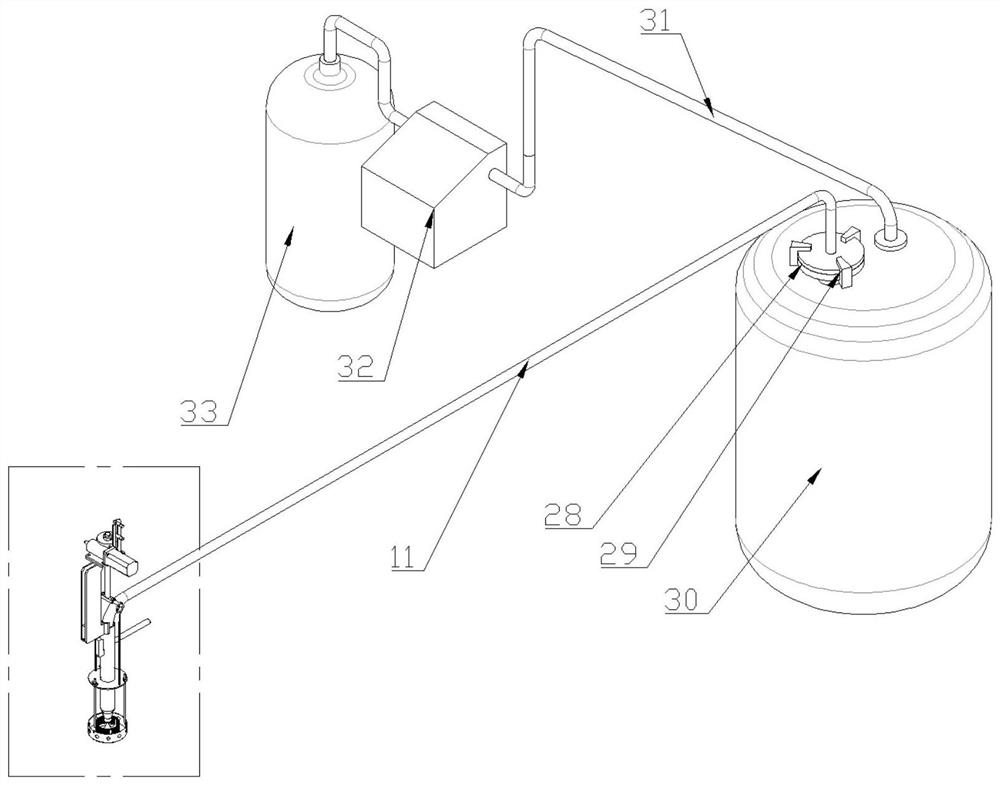
[0072] A liquid guide device for stable flow control in the semi-continuous casting process of magnesium alloys, the schematic diagram of which is shown in figure 1 , in the semi-continuous casting, comprise the crucible 30 that is filled with magnesium alloy, guide tube 11, crystallizer, guide tube 11 is square hook shape, is divided into short end (inlet end), long end (outlet end) and the middle liquid guide main pipe; the outer side of the liquid guide tube is welded with a stainless steel sleeve slightly larger than the diameter of the guide tube, and the liquid guide tube extends to the crucible 30 filled with magnesium alloy, and the port is located below the magnesium alloy. The liquid inlet end of the catheter is sealed by the sealing flange 28 and the crucible, and fixed by the concave buckle 29; A protective gas control device 32 is arranged on the top, and the protective gas control device 32 is used to control the internal pressure of the crucible by adjusting the...

Embodiment 2

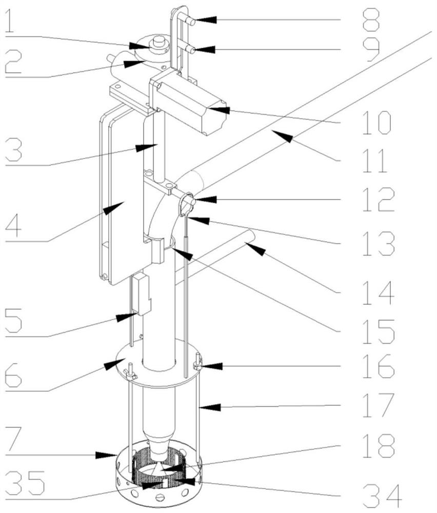
[0090] A liquid guiding device for stabilizing and controlling flow in the semi-continuous casting process of magnesium alloys in this embodiment is the same as that in Embodiment 1, except that the hanging beam adjustment part used is a manual hanging beam adjusting part, and the liquid guiding control actuator Partial enlarged picture is Figure 4 , the difference is:

[0091] The lifting device in the liquid guiding control executive mechanism includes the quick-hanging support arm 4, the hanging beam 12, the positioning block 21, the lifting rod 3 and the manual hanging beam adjusting part, and the manual hanging beam adjusting part includes a fine-tuning bolt 22, an adjusting rod 23, a shaft Pin 24, steel block 38, fast-falling pad iron 25, fast-falling pad iron nut 26, fast-falling pad iron screw rod 27; the adjusting rod 23 is connected with the quick-hanging support arm 4 through the pivot pin 24, and one end of the adjusting rod 23 is a suspension The beam 12 and the...

Embodiment 3

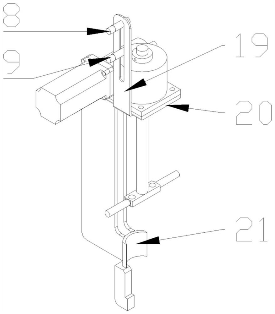
[0096] Embodiment 1 of the present invention is an electric liquid guiding device with a rectangular shunt tank, and its control shunting device is as follows: Figure 5 shown.

[0097] In this embodiment, a liquid guiding device for stabilizing and controlling flow in the semi-continuous casting process of magnesium alloys is provided with a liquid guiding control actuator and a protective gas control device at the liquid outlet of the catheter tube. The liquid guiding control actuator can be divided into electric guiding The liquid control device and the manual liquid control device; the electric liquid control device uses the motor and the limit switch to realize the liquid control; the manual liquid control device is slightly different from the electric liquid control device, and the lever principle is used to realize the liquid control;

[0098] This embodiment is an electric catheter control device. In this embodiment, the catheter is in the shape of a square hook, and i...


PUM


Abstract

The invention discloses a liquid guide device and method for stabilizing and controlling flow in a magnesium alloy semi-continuous casting process, belonging to the field of casting. The liquid guide device for stable flow control in the semi-continuous casting process of magnesium alloy is provided with a liquid guide control actuator and a protective gas control device; The device is used to adjust and control the rise and fall of the shunt device, and the control shunt device is used to control the flow rate of the magnesium alloy melt at the liquid end of the catheter; the crucible containing the magnesium alloy and the protective gas storage tank are connected through the protective gas pipeline, and the protective gas pipeline There is a shielding gas control device on it, which is used to control the pressure inside the crucible by adjusting the shielding gas output flow. The device can stably transmit the high-temperature melt during the semi-continuous casting process, ensure the stability of the liquid level in the mold, improve the surface quality and smoothness of the product, reduce the possibility of slag inclusion, and realize stable and safe casting production. wide.

Description

technical field [0001] The invention belongs to the technical field of casting, and in particular relates to a liquid guiding device and method for stabilizing and controlling flow in a magnesium alloy semi-continuous casting process. Background technique [0002] For the traditional ingot casting method, steel mold casting is adopted. However, the ingot produced by this method has relatively coarse grains, poor structure uniformity, and defects such as slag inclusion are prone to occur. The crystal grains of the magnesium alloy billet produced by the semi-continuous casting process are obviously refined, and the uniformity and density of the alloy structure are improved, thereby improving the mechanical properties and productivity of the product. [0003] Due to the excellent properties of magnesium alloys, it is particularly important to be able to produce magnesium alloy ingots with good casting properties. In recent years, discussions on how to improve the casting perfo...

Claims


Application Information

Patent Timeline
Patent Type & Authority Patents(China)
IPC IPC(8): B22D11/103B22D11/18
CPCB22D11/001B22D11/103B22D11/18
Inventor 乐启炽闫家仕程春龙李多娇陈亮王彤赵大志宝磊周伟阳蒋燕超
Owner NORTHEASTERN UNIV LIAONING
Why Eureka
Try Eureka