
Optical fiber arrangement mechanism for communication equipment and arrangement method thereof

A technology of communication equipment and finishing mechanism, which is applied in the fiber mechanical structure, light guide, optics, etc., can solve the problems of reducing the fiber finishing speed, the fiber is easily broken and damaged, and the finishing is time-consuming and laborious. clean effect

Inactive Publication Date: 2021-08-17
BEIJING UXSINO SOFTWARE
View PDF0 Cites 0 Cited by
  • Summary
  • Abstract
  • Description
  • Claims
  • Application Information

AI Technical Summary

Problems solved by technology

[0003] Existing communication equipment needs to connect a large number of optical fibers when using them. The optical fibers are scattered, and it is inconvenient to arrange the optical fibers artificially. The application proposes an optical fiber finishing mechanism and its finishing method for communication equipment to meet the needs

Method used


Image

  • Optical fiber arrangement mechanism for communication equipment and arrangement method thereof
  • Optical fiber arrangement mechanism for communication equipment and arrangement method thereof
  • Optical fiber arrangement mechanism for communication equipment and arrangement method thereof

Examples


Embodiment

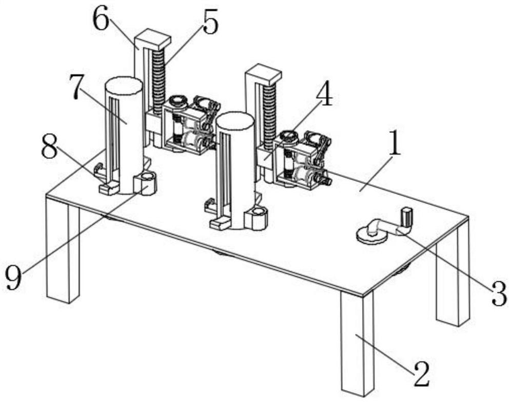
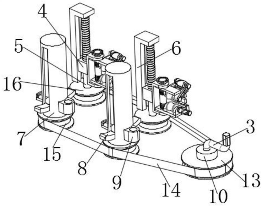
[0046] Example: Reference Figure 1-9 The shown optical fiber arrangement mechanism and method for communication equipment includes a fixed base 1, and two L-shaped fixed plates 6 are fixedly installed on the top of the fixed base 1, and the L-shaped fixed plates 6 can be used in the prior art Any metal plate, which is welded to the top of the fixed base 1 for fixing. The bottoms of the two L-shaped fixed plates 6 and the top of the fixed base 1 are correspondingly rotated with two movable screw rods 5, and the optical fiber position adjustment parts are installed on the two movable screw rods 5, and the top of the fixed base 1 is rotated and installed with two A rotating rod 7, two rotating rods 7 and two movable screw mandrels 5 are connected through a transmission unit, and an optical fiber take-out unit is installed on the two rotating rods 7. Through the setting of the optical fiber position adjustment part, the optical fiber arrangement mechanism can quickly arrange the...


PUM


Abstract

The invention discloses an optical fiber arrangement mechanism for communication equipment and an arrangement method thereof, and relates to the technical field of optical fiber arrangement mechanisms, the optical fiber arrangement mechanism comprises a fixed base, and the top of the fixed base is fixedly provided with two L-shaped fixed plates; the bottoms of the two L-shaped fixing plates and the top of the fixing base are correspondingly and rotatably provided with two movable lead screws, the two movable lead screws are both provided with optical fiber position adjusting parts, and the top of the fixing base is rotatably provided with two rotating rods. The invention further discloses an optical fiber arrangement method for the communication equipment. According to the optical fiber arrangement mechanism for the communication equipment and the arrangement method thereof, the optical fiber position adjusting part is arranged, so that the optical fiber arrangement mechanism can quickly arrange the optical fibers, the optical fibers cannot be scattered, multiple optical fibers can be arranged at the same time, the arrangement speed of the optical fibers is increased, time and labor are saved, and the optical fibers cannot be wound mutually; and the optical fibers are effectively protected from being broken and damaged in the arrangement process.

Description

technical field [0001] The invention relates to the technical field of optical fiber arrangement mechanisms, in particular to an optical fiber arrangement mechanism and an arrangement method for communication equipment. Background technique [0002] Optical fiber is the abbreviation of optical fiber. It is a fiber made of glass or plastic. It can be used as a light transmission tool. The transmission principle is the total reflection of light. Conduction is much less lossy, and communication devices use optical fibers to transfer information. [0003] Existing communication equipment needs to connect a large number of optical fibers when using them. The optical fibers are scattered, and it is inconvenient to arrange the optical fibers artificially. The application proposes an optical fiber arrangement mechanism and arrangement method for communication equipment to meet the requirements. Contents of the invention [0004] The purpose of the present application is to provi...

Claims


Application Information

Patent Timeline
Patent Type & Authority Applications(China)
IPC IPC(8): G02B6/44
CPCG02B6/4439G02B6/444
Inventor 逯瑶
Owner BEIJING UXSINO SOFTWARE
Learn More