
Projection module and projector

A projection module and projector technology, which is applied in the field of projectors, can solve the problems of reducing the volume of the whole machine, achieve the effects of reducing the back focus, reducing production costs, and improving production difficulty

Pending Publication Date: 2021-08-10
NANHUA INTELLIGENT PRECISION MACHNE (SHENZHEN) CO LTD
View PDF2 Cites 1 Cited by
  • Summary
  • Abstract
  • Description
  • Claims
  • Application Information

AI Technical Summary

Problems solved by technology

[0008] The purpose of the present invention is to overcome the light combination problem caused by the large size of the domestic LCD light valve, so that the X prism of the 3LCD projector or the light combination device of the 2LCD projector can be made easily and cheaply, and at the same time, it is beneficial to the reduction of the overall size. The size of the machine, changing the shape of the whole machine to stack, and reducing the production cost of the projection lens are also positively helpful.

Method used


Image

  • Projection module and projector
  • Projection module and projector
  • Projection module and projector

Examples


Embodiment 1

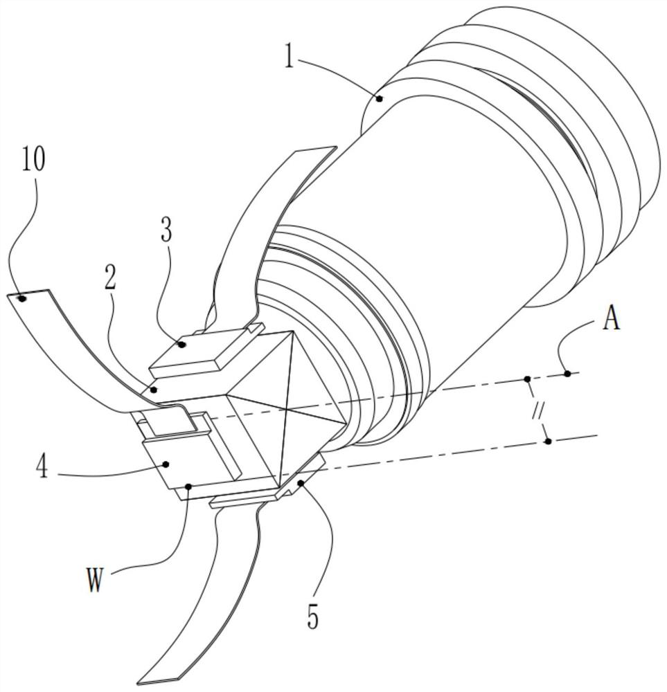
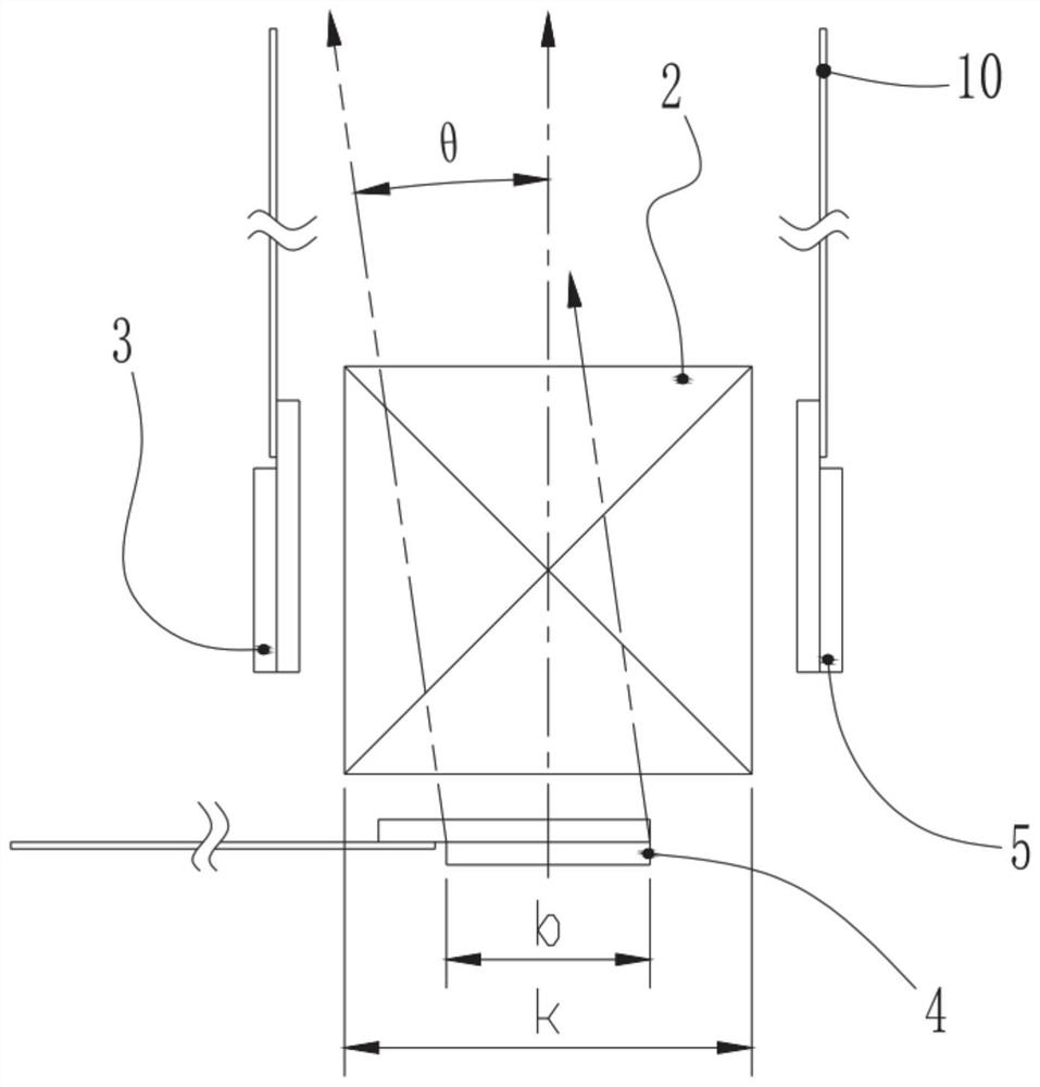
[0035] See figure 1 , image 3 and Figure 4 As shown, a projection module provided in this embodiment includes a transmissive LCD light valve, a light combining device and a projection lens 1, and the number of the LCD light valves is three; the light combining device is an X prism 2; The long side W of the display window of any LCD light valve is parallel to the central intersection line A of the X prism 2; The green field LCD light valve 4 of the image and the blue field LCD light valve 5 for displaying the blue field image; the opposite sides of the X prism 2 are respectively provided with the green field LCD light valve 4 and the projection lens 1 .

[0036] In the present embodiment, the red field LCD light valve 3, the green field LCD light valve 4 and the blue field LCD light valve 5 are installed near the three incident surfaces of the X prism 2 (the specific position is determined by the back focal length and relative position of the projection lens 1, The lengt...

Embodiment 2

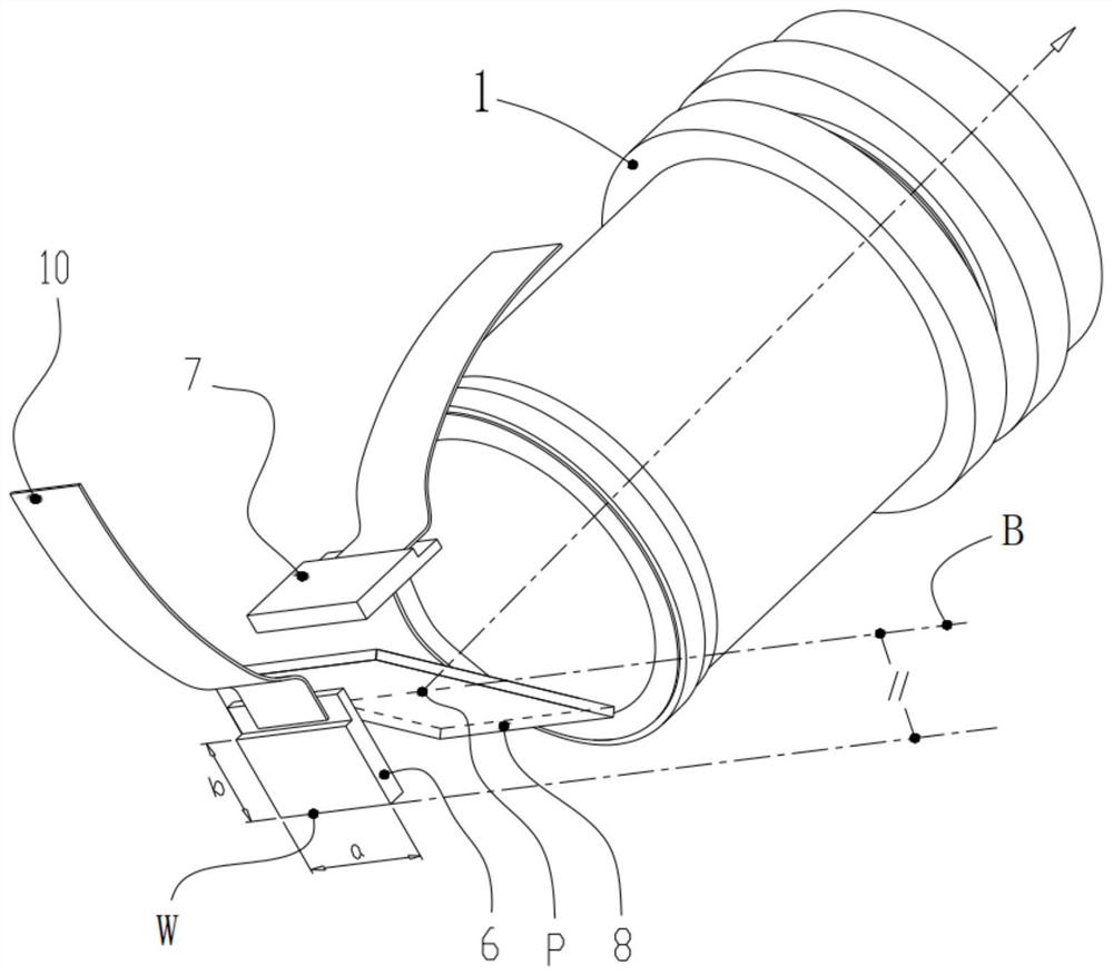
[0047] see figure 2 , a projection module provided in this embodiment includes a transmissive LCD light valve, a light combination device and a projection lens 1, the number of the LCD light valves is two, and the two LCD light valves are respectively the first LCD light valve valve 6 and the first LCD light valve 7.

[0048] The light emitted by the first LCD light valve 6 among the two LCD light valves passes through the light combining device 8 and the projection lens 1 in sequence and then projected; the light emitted by the second LCD light valve 7 passes through the light combining device 8 is reflected and overlapped with the light of the first LCD light valve 6 passing through the light combination device 8 and then projected out through the projection lens 1; The intersection point of the reflective surface where the light is reflected and the optical axis of the projection lens 1 is P, and on the reflective surface, a straight line passing through point P and paral...

Embodiment 3

[0056] This embodiment also provides a projector, including the projection module described in Embodiment 1 and Embodiment 2, wherein when the number of LCD light valves is three, the corresponding projector is a 3LCD projector; when the number of LCD light valves When the quantity is two pieces, the corresponding projector is a 2LCD projector.


PUM


Abstract

The invention discloses a projection module, which comprises two or three transmission-type LCD light valves, a light combining device and a projection lens. When the number of the LCD light valves is three, the light combining device is an X prism, and the long side W of the display window of any LCD light valve is parallel to the central intersecting line A of the X prism; and when the number of the LCD light valves is two, light emitted by the first LCD light valve penetrates through the light combining device, and light emitted by the second LCD light valve is reflected by the light combining device. The invention further discloses a projector which comprises the projection module. The manufacturing difficulty of the light combining device can be obviously improved, the relatively low manufacturing cost can be realized, the size of the whole machine can be reduced, the appearance stacking of the whole machine can be changed, the manufacturing cost of the projection lens can be reduced, and the product competitiveness can be improved.

Description

technical field [0001] The invention relates to the field of projectors, in particular to a projection module and an LCD projector. Background technique [0002] Such as Figure 5-8 As shown, in a traditional 3LCD projector, the arrangement of the LCD light valve and the light combining device is such that the short side H' of the display window of any LCD light valve is parallel to the intersection line A' of the center of the X prism 2'. In the figure, 1' is the projection lens, 2' is the X prism, 3', 4', and 5' correspond to the LCD light valves displaying red, green, and blue field images respectively, and 50 is the FPC (Flexible Printed Circuit) of the LCD light valve Arranging lines, / / is a parallel symbol (the same below). This ranking method is determined by the development direction and historical accumulation of foreign 3LCD projection technology. In the past 30 years, the size of LCD light valves based on HTPS (High Temperature Poly-Silicon) technology has beco...

Claims


Application Information

Patent Timeline
Patent Type & Authority Applications(China)
IPC IPC(8): G03B21/00
CPCG03B21/006G03B21/28G03B33/12
Inventor 郭瀚文
Owner NANHUA INTELLIGENT PRECISION MACHNE (SHENZHEN) CO LTD
Learn More