Low-energy-consumption cooling tower cleaning device

A cleaning device and cooling tower technology, which is applied in the direction of cleaning heat transfer devices, non-rotating equipment cleaning, flushing, etc., can solve the problems of not having a cleaning box, increasing labor intensity, and not being able to flush with water cooling towers in time, so as to achieve convenient use , to achieve the effect of water level monitoring

Inactive Publication Date: 2021-08-10
江西方舟流体科技有限公司
View PDF1 Cites 1 Cited by
  • Summary
  • Abstract
  • Description
  • Claims
  • Application Information

AI Technical Summary

Problems solved by technology

[0002] Cooling tower, its cooling is to use water and air flow to exchange heat and cold to generate steam, and steam volatilizes to take away heat to achieve evaporation heat dissipation, convective heat transfer and radiation heat transfer to dissipate waste heat generated in industry or in refrigeration and air conditioning To reduce the water temperature of the evaporative cooling device to ensure the normal operation of the system, the cooling tower needs to be cleaned regularly. The traditional cleaning method is to clean it manually, which increases the labor intensity of people.
[0003] Patent application CN212664430U, publication date 20210309, discloses a cooling tower cleaning device, including a fixed seat, the top of the fixed seat is fixedly installed with a cabinet, the inside of the cabinet is fixedly installed with a hydraulic rod, and the bottom of the hydraulic rod is fixed A connection plate is connected, the middle part of the lower surface of the connection plate is fixedly installed with a first motor, the output end of the first motor is fixedly connected with a cross bar, and both ends of the cross bar are plugged with movable rods. A second motor is fixedly installed on the upper surface of the movable rod, and the output end of the second motor is fixedly connected with a cleaning cylinder. The present invention can drive the cleaning cylinder to clean the cooling tower through the second motor, and drive the horizontal bar to rotate through the first motor. , so that the cross bar drives the cleaning cylinder to do circular motion, saving time and effort. Adjust the height of the cleaning cylinder through the setting of the hydraulic rod to improve the cleaning effect. Adjust the spacing of the cleaning cylinder through the movable rod, which is convenient for cleaning cooling towers of different specifications and improves the cleaning effect. Practicality, however, the device is not equipped with a cleaning tank and cannot flush the cooling tower with water in time

Method used


Image

  • Low-energy-consumption cooling tower cleaning device
  • Low-energy-consumption cooling tower cleaning device
  • Low-energy-consumption cooling tower cleaning device

Examples


Embodiment Construction

[0058] All features disclosed in the present invention, or steps in all methods or processes disclosed, may be combined in any way, except for mutually exclusive features and / or steps.

[0059] Any feature disclosed in this specification (including any appended claims, abstract and drawings), unless expressly stated otherwise, may be replaced by alternatives which are equivalent or serve a similar purpose. That is, unless expressly stated otherwise, each feature is one example only of a series of equivalent or similar features.

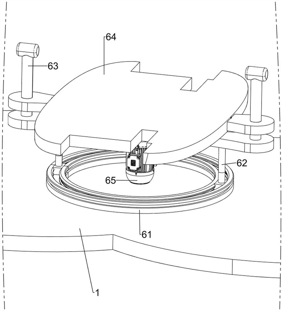
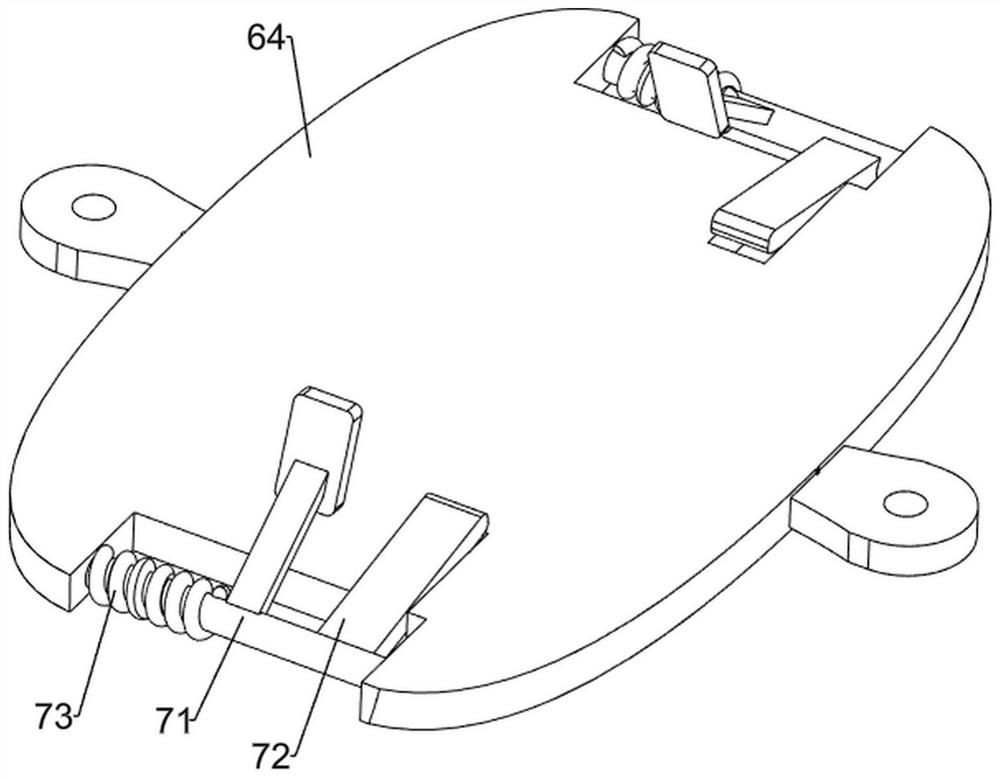
[0060] Below will combine the appended in the embodiment of the present invention Figure 1 to Figure 7 The technical solutions in the novel embodiments are clearly and completely described. Obviously, the described embodiments are only some embodiments of the present invention, rather than all the embodiments. Based on the embodiments of the present invention, all other embodiments obtained by persons of ordinary skill in the art without making crea...


PUM


Abstract

The invention relates to a cleaning device, in particular to a low-energy-consumption cooling tower cleaning device. The low-energy-consumption cooling tower cleaning device is convenient to operate, capable of reducing the labor intensity of people and low in manufacturing cost. The low-energy-consumption cooling tower cleaning device comprises: a first base and first supporting frames, wherein the first supporting frames are arranged on the two sides of the first base respectively; a second supporting frame, arranged on the upper side of the first supporting frame on one side; a placing frame, arranged between the upper sides of the two first supporting frames; a cleaning box, arranged in the placing frame; a rotating mechanism, arranged on the first base; and a clamping mechanism, arranged on the rotating mechanism. An output shaft of a motor rotates to drive a second base to rotate so as to drive a cooling tower to rotate, the second base drives a fixing rod to rotate so as to drive a slider to slide, and the cooling tower rotates so that cleaning can be conducted in a larger range, and the rotating effect is achieved.

Description

technical field [0001] The invention relates to a cleaning device, in particular to a low energy consumption cooling tower cleaning device. Background technique [0002] Cooling tower, its cooling is to use water and air flow to exchange heat and cold to generate steam, and steam volatilizes to take away heat to achieve evaporation heat dissipation, convective heat transfer and radiation heat transfer to dissipate waste heat generated in industry or in refrigeration and air conditioning To reduce the water temperature of the evaporative heat dissipation device to ensure the normal operation of the system, the cooling tower needs to be cleaned regularly. The traditional cleaning method is to clean it manually, which increases the labor intensity of people. [0003] Patent application CN212664430U, publication date 20210309, discloses a cooling tower cleaning device, including a fixed seat, the top of the fixed seat is fixedly installed with a cabinet, the inside of the cabine...

Claims


Application Information

Patent Timeline
Patent Type & Authority Applications(China)
IPC IPC(8): F28G13/00F28G9/00F28G1/02F28G15/02F28G15/00
CPCF28G1/02F28G9/00F28G13/00F28G15/003F28G15/02
Inventor 周武平谢茂华
Owner 江西方舟流体科技有限公司
Why Eureka
Try Eureka