Portable positioning pin removal device and using method thereof
A positioning pin and portable technology, which is applied in the field of portable positioning pin removal devices, can solve the problems of unstable assembly and positioning of components and low efficiency, and achieve the effects of reducing labor intensity of workers, facilitating disassembly and replacement, and prolonging service life
- Summary
- Abstract
- Description
- Claims
- Application Information
AI Technical Summary
Problems solved by technology
Method used
Image
Examples
Embodiment 1
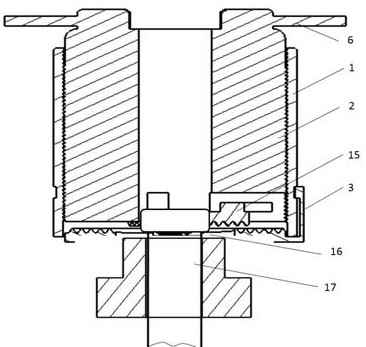
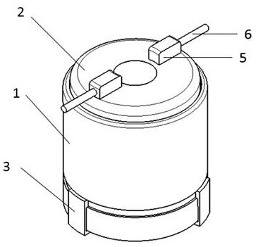
[0038] As a basic embodiment of the present invention, the present invention includes a portable positioning pin removal device, which includes a housing 1 , an inner shaft 2 , a base 3 , claws 15 and a force applying rod 6 . A screw transmission is formed between the inner shaft 2 and the outer shell 1, and mutual translation in the direction of the coaxial line is realized through relative rotation. The inner shaft 2 is provided with an inner shaft lug 5 , and the force applying rod 6 is fixedly connected with the inner shaft lug 5 . The base 3 can realize rotational movement along the casing 1 . The bottom end surface of the inner shaft 2 is provided with six guide grooves 8 evenly distributed along the axis, and the number of the claws 15 is the same as that of the guide grooves 8 . The claw 15 is provided with a claw boss 12 , and the claw boss 12 and the guide groove 8 form a moving pair, so that the claw 15 can move radially along the guide groove 8 . The inner surfac...
Embodiment 2
[0040] As a preferred embodiment of the present invention, the present invention includes a portable positioning pin removal device, which includes a housing 1 , an inner shaft 2 , a base 3 , claws 15 and a force applying rod 6 . A screw transmission is formed between the inner shaft 2 and the outer shell 1, and mutual translation in the direction of the coaxial line is realized through relative rotation. The force applying rod 6 is a telescopic structure, the inner shaft 2 is provided with an inner shaft lug 5 , and the force applying rod 6 is threadedly connected with the inner shaft lug 5 . The base 3 can realize rotational movement along the casing 1 .
[0041] The bottom end surface of the inner shaft 2 is provided with a guide groove 8 uniformly distributed along the axis, and the number of the claws 15 is the same as that of the guide groove 8 . The claw 15 is provided with a claw boss 12, and the guide groove 8 is provided with a radial limit surface 18, and the claw ...
Embodiment 3
[0044] As another preferred embodiment of the present invention, the present invention includes a portable positioning pin removal device, which includes a housing 1 , an inner shaft 2 , a base 3 , claws 15 and a force applying rod 6 . A screw transmission is formed between the inner shaft 2 and the outer shell 1, and mutual translation in the direction of the coaxial line is realized through relative rotation. The inner shaft lug 5 is arranged on the inner shaft 2 , and the force applying rod 6 is connected with the inner shaft lug 5 . The base 3 can realize rotational movement along the casing 1 .
[0045]The bottom end surface of the inner shaft 2 is provided with four guide grooves 8 evenly distributed along the axis, and the number of the claws 15 is the same as that of the guide grooves 8 . The claw 15 is provided with a claw boss 12, and the claw boss 12 and the guide groove 8 form a moving pair, so that the claw 15 can move radially along the guide groove 8 by rolling...
PUM
 Abstract
Description
Claims
Application Information
 - Generate Ideas
- Intellectual Property
- Life Sciences
- Materials
- Tech Scout
- Unparalleled Data Quality
- Higher Quality Content
- 60% Fewer Hallucinations
Browse by: Latest US Patents, China's latest patents, Technical Efficacy Thesaurus, Application Domain, Technology Topic, Popular Technical Reports.
© 2025 PatSnap. All rights reserved.Legal|Privacy policy|Modern Slavery Act Transparency Statement|Sitemap|About US| Contact US: help@patsnap.com


