a fire fighting robot
A technology of fire-fighting robot and robot body, which is applied in fire rescue and other directions to achieve the effect of improving fire-fighting efficiency and fire-fighting effect, and facilitating rapid dredging
- Summary
- Abstract
- Description
- Claims
- Application Information
AI Technical Summary
Problems solved by technology
Method used
Image
Examples
Embodiment 1
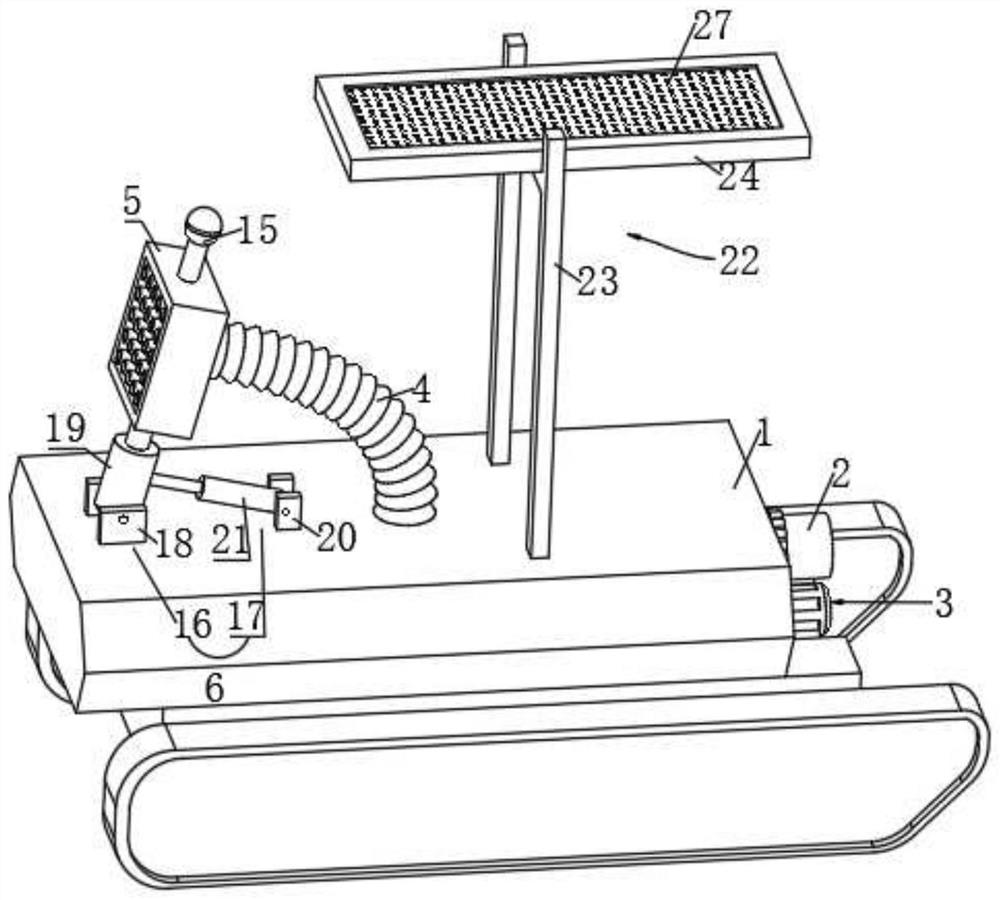
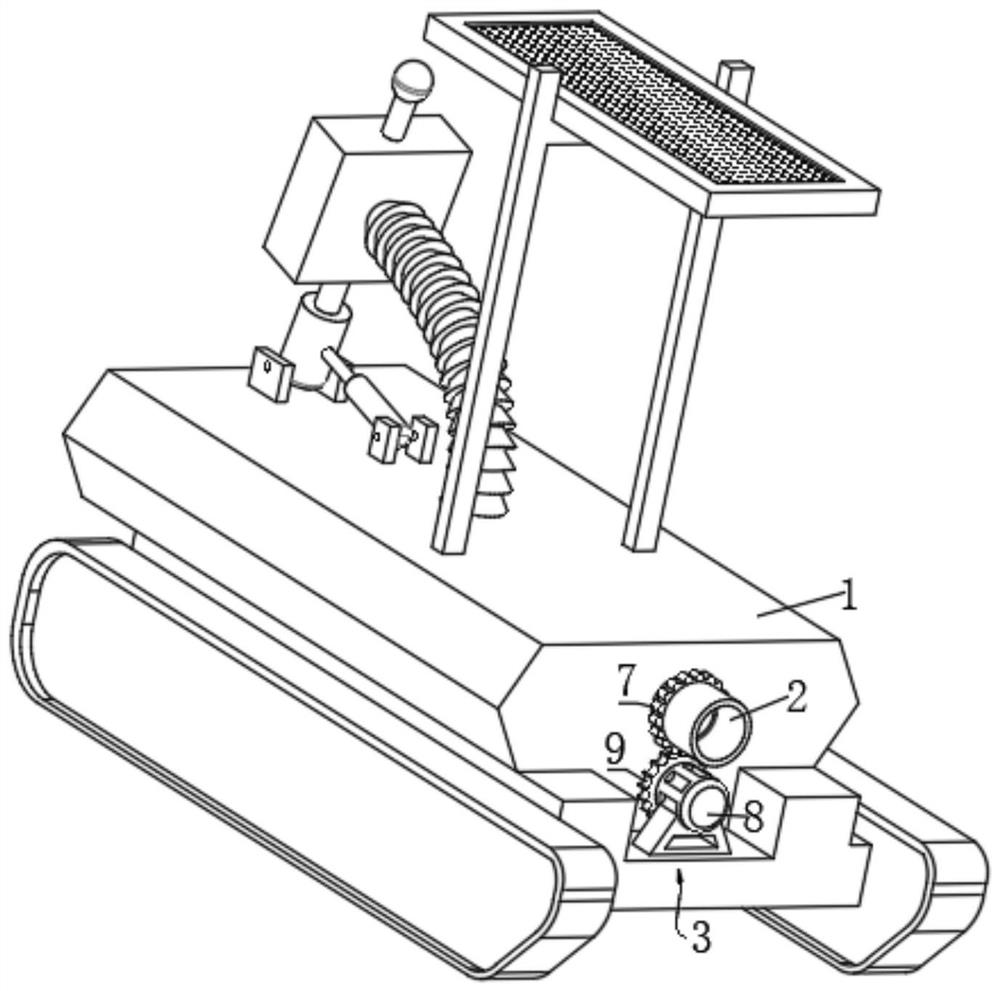
[0036] see figure 1 , the embodiment of the present invention provides a technical solution: a fire-fighting robot, including a robot body 1, a water pipe joint 2 is rotatably connected to the tail side of the robot body 1, and a water pipe joint 2 is installed on the water pipe joint 2 for driving the The drive mechanism 3 for the rotation of the water pipe joint 2;
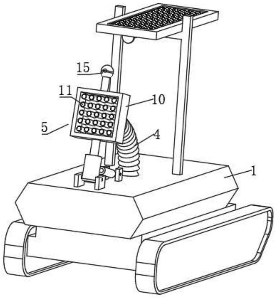
[0037] The upper surface of the robot body 1 is connected with an injector 5 for adjusting the spray range through a universal hose 4;
[0038] An adjusting mechanism 6 for adjusting the spraying angle of the injector 5 is also installed on the robot body 1 .
[0039] It is not difficult to find from the above content that when the fire fighting robot of the present application is used for fire fighting work, the firefighters can connect the water pipe joint 2 with the fire fighting water pipe, and the fire fighting water will pass through the fire joint 2 and the injector 5 connected by the universal hose 4 I...
Embodiment 2
[0049] like figure 1 As shown, the same or corresponding components as those in the first embodiment are given the corresponding reference numerals as in the first embodiment. For the sake of brevity, only the points of difference from the first embodiment are described below. The difference between the second embodiment and the first embodiment is:
[0050] like figure 1 , the adjusting mechanism 6 includes a first adjusting component 16 for adjusting the height of the injector 5 and a second adjusting component 17 for adjusting the injection angle of the injector 5;
[0051] It is worth noting that the injection height of the injector 5 can be adjusted by using the first adjustment component 16, and the injection direction of the injector 5 can be easily adjusted with the cooperation of the second adjustment component 17, and the fire fighting in the required direction can be realized. Water jet works.
[0052] The first adjustment assembly 16 includes a first mounting se...
Embodiment 3
[0057] like figure 1 , 4 and 5, in which the same or corresponding components as in the first embodiment are given the corresponding reference numerals with the first embodiment. For the sake of simplicity, only the differences from the first embodiment are described below. The difference between the third embodiment and the first embodiment is:
[0058] like figure 1 and 4 As shown, above the ejector 5 is also provided with a block assembly 22 for shielding the top of the ejector 5 , and the block assembly 22 includes an H-shaped tripod connected to the top of the robot body 1 . 23. The baffle 24 slidably mounted on the inner side of the top of the H-shaped tripod 23 and the third push rod motor 25 installed on the H-shaped tripod 23. The bottom side of the H-shaped tripod 23 is provided with a fixed seat 26, the power output end of the third push rod motor 25 is connected to the fixed seat 26, and a grid 27 is provided on the inner side of the blocking frame 24;
[0059...
PUM
 Abstract
Description
Claims
Application Information
 - R&D
- Intellectual Property
- Life Sciences
- Materials
- Tech Scout
- Unparalleled Data Quality
- Higher Quality Content
- 60% Fewer Hallucinations
Browse by: Latest US Patents, China's latest patents, Technical Efficacy Thesaurus, Application Domain, Technology Topic, Popular Technical Reports.
© 2025 PatSnap. All rights reserved.Legal|Privacy policy|Modern Slavery Act Transparency Statement|Sitemap|About US| Contact US: help@patsnap.com


