Internet intelligent sound box with self-adsorption function
A smart speaker and Internet technology, applied to color TV parts, TV system parts, transducer housing/cabinet/bracket, etc., can solve the problems of single function, inconvenient fixing, etc., and achieve easy movement, efficiency, The effect of strong practicability and balanced force
- Summary
- Abstract
- Description
- Claims
- Application Information
AI Technical Summary
Problems solved by technology
Method used
Image
Examples
Embodiment 1
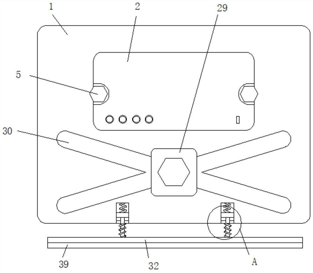
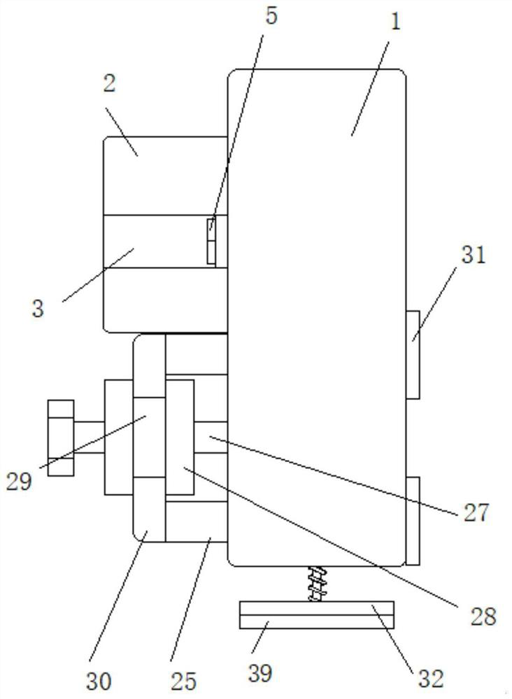
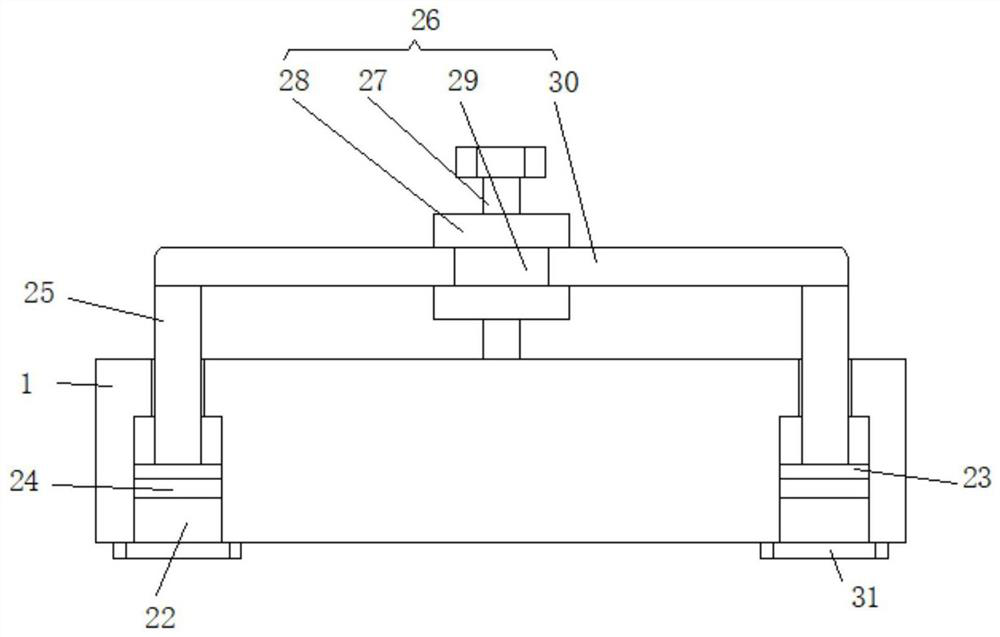
[0030] Embodiment one, such as Figure 1-7 As shown, an Internet smart speaker with self-adsorption function includes a vertically arranged fixed plate 1, a speaker body 2 is arranged on one side of the fixed plate 1, the speaker body 2 is in contact with the fixed plate 1, and the two ends of the speaker body 2 are symmetrical There are two installation slots 3, and the inner walls of the two installation slots 3 are provided with installation holes 4. Two installation screws 5 are symmetrically arranged at both ends of the speaker body 2, and the two installation screws 5 respectively penetrate through the corresponding installation holes 4 on the same side and Slidingly connected with it, the two mounting screws 5 are threadedly connected with the fixed plate 1, the inner bottom surface of the speaker body 2 is rotatably connected with a main shaft 6, the main shaft 6 is vertically arranged, the main shaft 6 is perpendicular to the inner bottom surface of the sound box body ...
Embodiment 2
[0031] Embodiment two, such as Figure 5 , 6 As shown, the drive mechanism 8 includes a motor 14 fixedly connected to the inner bottom surface of the speaker body 2, the shaft of the motor 14 is fixedly connected with a driving gear 15, and the driving gear 15 is meshed with the driven gear 7, and the radius of the driving gear 15 is smaller than the radius of the driven gear. , The motor 14 uses a servo motor that can be rotated forward and backward, and the rotation of the motor 14 allows the camera 10 to be rotated and adjusted, so that the camera 10 can be used to shoot in different directions, and the function is more powerful.
Embodiment 3
[0032] Embodiment three, such as Figure 5 , 6 As shown, the adjustment mechanism 11 includes a synchronous plate 16 fixedly connected to the main shaft 6. The synchronous plate 16 is L-shaped. The side of the synchronous plate 16 facing the main shaft 6 is fixedly connected with an electric telescopic rod 17. The electric telescopic rod 17 is arranged horizontally. The rod 17 and the support member 13 are located on the same side, the free end of the electric telescopic rod 17 is fixedly connected with an engaging rod 18, and the end of the connecting rod 18 away from the electric telescopic rod 17 is fixedly connected with a drive shaft 19 arranged horizontally, and the driving shaft 19 and the connecting rod 18 is vertical, one side of the connecting rod 9 is fixedly connected with a drive plate 20, the drive plate 20 is parallel to the connecting rod 9, and the drive plate 20 is provided with a drive groove 21, and the drive shaft 19 is embedded in the drive groove 21 and is...
PUM
 Abstract
Description
Claims
Application Information
 - R&D
- Intellectual Property
- Life Sciences
- Materials
- Tech Scout
- Unparalleled Data Quality
- Higher Quality Content
- 60% Fewer Hallucinations
Browse by: Latest US Patents, China's latest patents, Technical Efficacy Thesaurus, Application Domain, Technology Topic, Popular Technical Reports.
© 2025 PatSnap. All rights reserved.Legal|Privacy policy|Modern Slavery Act Transparency Statement|Sitemap|About US| Contact US: help@patsnap.com


