A network optical cable wiring equipment based on big data

A kind of wiring equipment and big data technology, applied in the direction of optical fiber/cable installation, separation method, dispersion particle separation, etc., can solve the problem of broken cable core, difficult control of bending radius of cable arrangement, heat accumulation on the surface of photoelectric composite cable, etc. problem, achieve the effect of reducing water content, avoiding warping or even broken core

Active Publication Date: 2022-04-01
ANQING NORMAL UNIV
View PDF0 Cites 0 Cited by
  • Summary
  • Abstract
  • Description
  • Claims
  • Application Information

AI Technical Summary

Problems solved by technology

[0003] However, in the long-term use of the existing technology, there are still certain disadvantages: 1. Whether it is a strong cable for power supply to equipment or a weak cable for communication wiring, during the pre-wiring lead wire process after taking the cable from vacuum packaging, A large amount of dust will be absorbed due to surface static electricity, which will cause heat accumulation on the surface of the photoelectric composite cable due to dust adhesion after the communication equipment is installed under high-load operation, which will affect the stability of the network; 2. Under the installation environment of different temperatures, The ductility of the cable skin and inner layer materials is different. When the bridge space encounters small-angle wiring, the bending radius of the cable group is not easy to control, and the compressive and tensile stresses on both sides of the inner and outer edges of the bending part of the cable row are uneven, resulting in It often occurs that the cable is warped after being fixed, or even the cable core is broken.

Method used


Image

  • A network optical cable wiring equipment based on big data
  • A network optical cable wiring equipment based on big data
  • A network optical cable wiring equipment based on big data

Examples


Embodiment Construction

[0021] In order to make the technical means, creative features, goals and effects achieved by the present invention easy to understand, the present invention will be further described below in conjunction with specific embodiments.

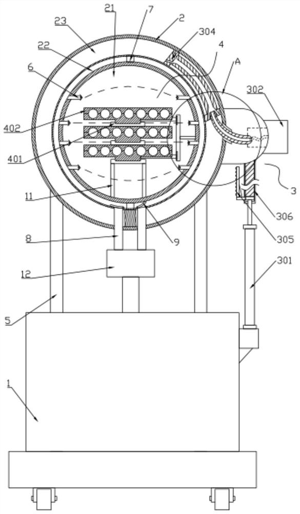
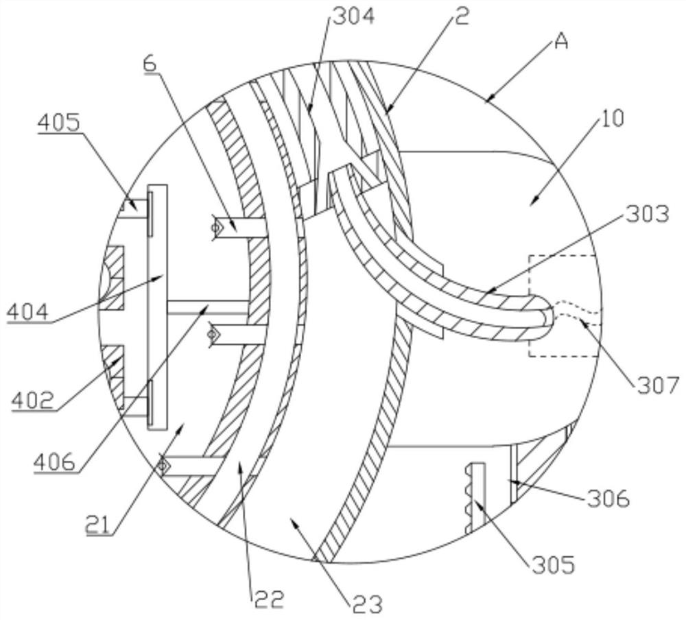
[0022] like Figure 1 to Figure 4 As shown, a network optical cable wiring device based on big data includes a trolley 1, an atomizing cylinder 2, a circulation mist removal mechanism 3, and a swing adjustment mechanism 4. The atomizing cylinder 2 is hollow and passes through a support rod 5 Fixed on the trolley 1, the atomizing cylinder 2 is sequentially divided into a mist discharge chamber 21, a storage chamber 22 and a sliding chamber 23 from inside to outside. Several spray heads 6 arranged side by side are installed on the mist discharge chamber 21. In the storage chamber 22, partition strips 7 are respectively arranged above and below, and the lower end of the storage chamber 22 is provided with two symmetrically arranged water outlet pipes...


PUM


Abstract

The invention discloses a network optical cable wiring device based on big data, relates to the technical field of cable wiring, and includes a trolley, an atomizing cylinder, a circulation mist removal mechanism and a swing adjustment mechanism. The present invention forms a local low-temperature steam and water mist circulation environment in the mist discharge chamber by setting a circulation mist discharge mechanism on the atomization cylinder, and quickly eliminates static electricity on both sides of the cable with a circular longitudinal section respectively, so as to realize the guarantee Reduce the water content in the network computer room under the premise of static electricity elimination and dust removal; by setting a swing adjustment mechanism in the mist removal chamber, during the process of cable pre-wiring, static electricity elimination and automatic wiring are carried out simultaneously. , within the allowable bending angle range, according to the installation conditions of the bridge, the real-time bending radius of the cable arrangement can be precisely controlled, and the compressive and tensile stress on both sides of the inner and outer edges of the bending part of the cable arrangement can be balanced simultaneously, so as to avoid warping or even Broken core and so on.

Description

technical field [0001] The invention relates to the technical field of cable wiring, in particular to a network optical cable wiring device based on big data. Background technique [0002] Since the big data modular network needs to complete data analysis such as fast calculation and efficient storage of data, there are many conventional components, and the number of cables connected to equipment is naturally more. At present, new types of photoelectric devices are commonly used in broadband access network systems. When the composite cable is pre-wired in the corresponding network computer room, the strong and weak current cables on the cable bridge are mostly transported to the network computer room through a vacuum environment, and after being automatically arranged in slots, they are fixed by nylon cable ties or buckles. [0003] However, in the long-term use of the existing technology, there are still certain disadvantages: 1. Whether it is a strong cable for power suppl...

Claims


Application Information

Patent Timeline
Patent Type & Authority Patents(China)
IPC IPC(8): G02B6/46B29C53/08B29C53/80H05F1/00B01D47/06
CPCG02B6/46B29C53/083B29C53/80H05F1/00B01D47/06
Inventor 周佳骏谢晋
Owner ANQING NORMAL UNIV
Why Eureka
Try Eureka