
Indoor unit control method and indoor unit

A control method and indoor unit technology, applied in the direction of airflow control components, heating and ventilation control systems, heating methods, etc., can solve the problems of high limitation of air-conditioning ion emission mode and inability to achieve more intelligent adjustment

Active Publication Date: 2021-08-06
QINGDAO HAIER AIR CONDITIONER GENERAL CORP LTD +2
View PDF6 Cites 1 Cited by
  • Summary
  • Abstract
  • Description
  • Claims
  • Application Information

AI Technical Summary

Problems solved by technology

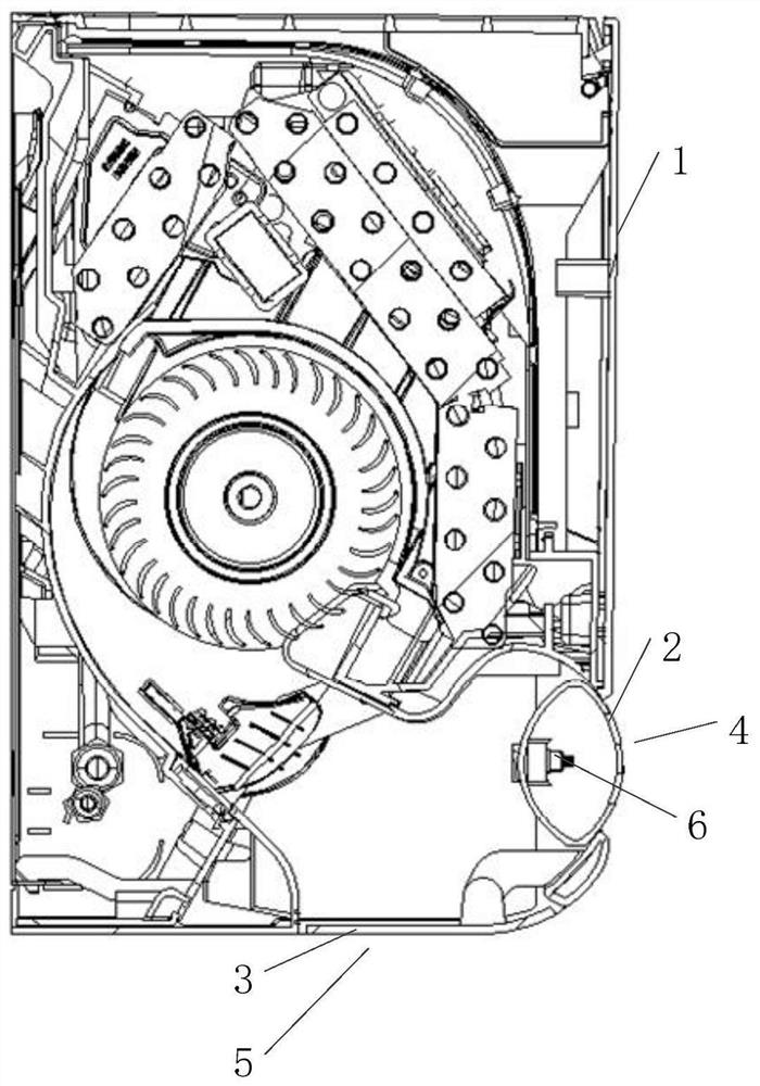
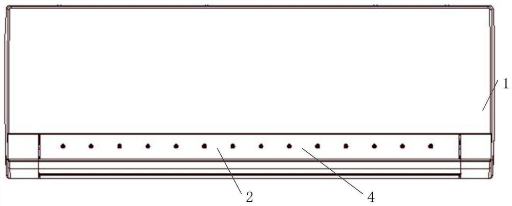
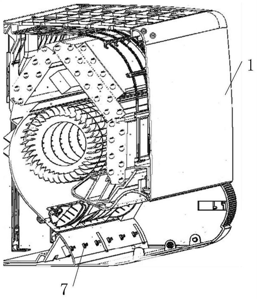
[0007] In order to solve the above-mentioned problems in the prior art, that is, in order to solve the problem that the operating mode, air supply mode and ion emission mode of the air conditioner have relatively high limitations and cannot achieve more intelligent adjustment, the present invention provides an indoor unit , including a housing, the housing is provided with a first air outlet and a second air outlet, the first air outlet faces to the front of the indoor unit, and the second air outlet faces to the bottom of the indoor unit; A windshield column, the windshield column is arranged at the first air outlet, and is slidably connected with the housing, so as to realize the opening and closing of the first air outlet and form a negative pressure area where air gathers; wind guide plate, the air deflector is arranged at the second air outlet, and the air deflector is rotatably mounted on the housing to realize the opening and closing of the second air outlet; the first ion emission module , the first ion emission module is arranged in the negative pressure area; the second ion emission module is arranged in the inside of the housing close to the position of the wind deflector; the personnel detection module, Used to detect the situation of indoor personnel; the personnel detection module communicates with the processor of the indoor unit

Method used


Image

  • Indoor unit control method and indoor unit
  • Indoor unit control method and indoor unit
  • Indoor unit control method and indoor unit

Examples


Embodiment Construction

[0048] Preferred embodiments of the present invention are described below with reference to the accompanying drawings. Those skilled in the art should understand that these embodiments are only used to explain the technical principles of the present invention, and are not intended to limit the protection scope of the present invention. Those skilled in the art can make adjustments as needed so as to adapt to specific applications. For example, although the indoor unit is used as an example in the description, the present invention can obviously be used in various other air supply devices as long as the air supply device has an air conditioning effect.

[0049] It should be noted that, in the description of the present invention, the terms "center", "upper", "lower", "left", "right", "vertical", "horizontal", "inner", "outer" etc. The terms of the indicated direction or positional relationship are based on the direction or positional relationship shown in the drawings, which a...


PUM


Abstract

The invention belongs to the technical field of air conditioning, and particularly provides an indoor unit control method and an indoor unit. The problems that the limitation of an air supply mode and an ion emission mode of an air conditioner is high, and intelligent adjustment cannot be achieved are solved. In order to achieve the purpose, the indoor unit is provided with two air outlets, the first air outlet is controlled through an air outlet baffle column, a first ion emission module is arranged in a negative pressure area formed by the air outlet baffle column, the second air outlet is controlled through an air guide plate, and a second ion emission module is arranged at the position, close to the air guide plate, inside a shell. The indoor unit control method comprises the steps that a control personnel detection module detects the indoor personnel condition; and according to the condition of indoor personnel, the position of the air outlet baffle column, opening and closing of the air guide plate and opening and closing of the first ion emission module and the second ion emission module are controlled, so that multiple different operation modes are achieved. The diversified operation modes of the indoor unit can be achieved according to the condition of indoor personnel.

Description

technical field [0001] The invention belongs to the technical field of air conditioning, and specifically provides an indoor unit control method and the indoor unit. Background technique [0002] With the development of the times and the advancement of technology, the use of air conditioners is becoming more and more popular, and people's demand for air conditioners is also increasing. It is not limited to simple temperature adjustment, but also intelligent control of air conditioners, indoor purification, and sterilization. And functions such as health care have new requirements. [0003] First of all, in the operating scenario of the air conditioner, there will be great differences in the indoor occupants. For example, in the scenario where there is one person in the room and multiple people in the room, if the same operating mode is used, the operating efficiency of the air conditioner will be low. And the problem of poor indoor personnel experience. Similarly, differen...

Claims


Application Information

Patent Timeline
IPC IPC(8): F24F1/0014F24F1/0076F24F13/14F24F11/65F24F11/79F24F11/64F24F8/30F24F120/12
CPCF24F1/0014F24F1/0076F24F13/1426F24F11/65F24F11/79F24F11/64F24F2120/12Y02B30/70
Inventor 郭嘉兴王宁
Owner QINGDAO HAIER AIR CONDITIONER GENERAL CORP LTD
Learn More