
Telescopic wide-angle LED light-emitting tube

A kind of LED light-emitting tube and telescopic technology, which is applied in the direction of semiconductor devices, light sources, and light source fixing of light-emitting elements, and can solve the problems of unable to maintain the brightness of the lamp beads, unable to protect the lamp beads, troubles, etc.

Inactive Publication Date: 2021-08-06
深圳市永裕光电有限公司
View PDF19 Cites 0 Cited by
  • Summary
  • Abstract
  • Description
  • Claims
  • Application Information

AI Technical Summary

Problems solved by technology

[0004] The purpose of the present invention is to provide a telescopic wide-angle LED light-emitting tube, which solves the problem that the existing wide-angle LED light-emitting tube cannot protect the lamp bead when it is not working; The range is determined by the brightness of the lamp bead. When adjusting the light range, the brightness of the lamp bead can only be changed by adjusting the voltage. It is impossible to adjust the light range while maintaining the brightness of the lamp bead; Installation and disassembly need to be realized with the help of electric soldering pen and solder paste, which is a troublesome problem

Method used


Image

  • Telescopic wide-angle LED light-emitting tube
  • Telescopic wide-angle LED light-emitting tube
  • Telescopic wide-angle LED light-emitting tube

Examples


Embodiment Construction

[0030] The technical solutions of the present invention will be clearly and completely described below in conjunction with the embodiments. Apparently, the described embodiments are only some of the embodiments of the present invention, not all of them. Based on the embodiments of the present invention, all other embodiments obtained by persons of ordinary skill in the art without creative efforts fall within the protection scope of the present invention.

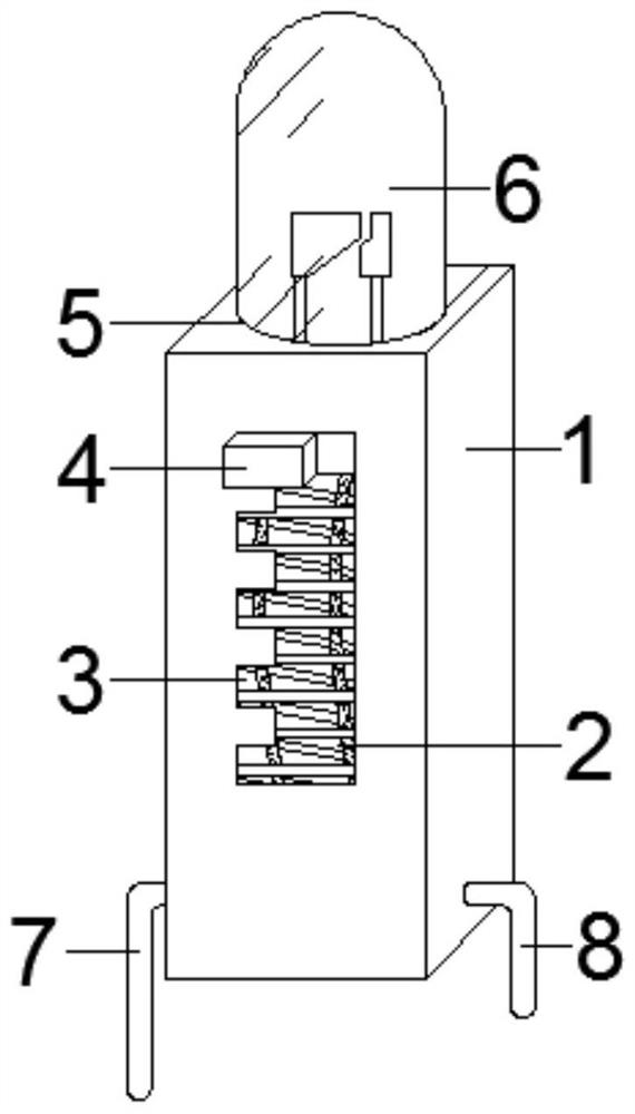
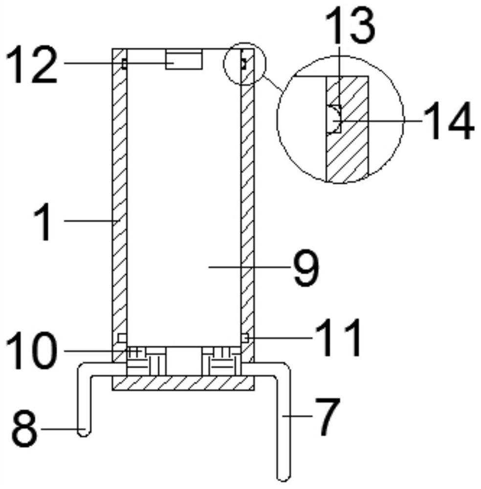
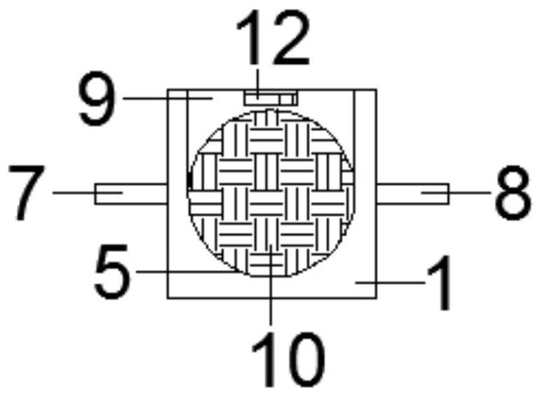
[0031] see Figure 1-7 As shown, a telescopic wide-angle LED light-emitting tube includes a protective box 1, a positive terminal 7 is provided on one side of the protective box 1 near the lower end, and a negative terminal 8 is provided on the other side of the protective box 1 near the lower end, which penetrates the protective box 1. There is an adjustment slot 2 on the front of the box 1, a tooth groove 3 is opened on the side of the adjustment slot 2 through the front of the protective box 1, and a limit hole 5 is open...


PUM


Abstract

The invention discloses a telescopic wide-angle LED light-emitting tube. The light-emitting tube comprises a protection box, a positive binding post is arranged in the position, close to the lower end, of one side of the protection box, a negative binding post is arranged in the position, close to the lower end, of the other side of the protection box, an adjusting groove is formed in the front surface penetrating through the protection box, a tooth groove is formed in the position, located on one side of the adjusting groove, of the front surface penetrating through the protection box, a limiting hole is formed in the center of the top end of the protection box in a penetrating mode, a lamp bead is arranged in the position, corresponding to the limiting hole, of the upper end of the protection box, a lower conducting strip is mounted at the bottom end in the protection box, an adjusting mechanism is arranged in the position, close to the edge, of the lower end of the lamp bead, a connecting mechanism is arranged in the center of the lower end of the lamp bead, a lead is mounted at the lower end of the connecting mechanism, the size of an adjusting button is matched with that of the tooth groove, and the adjusting button is arranged in a shifting manner. The illumination range of the lamp bead can be conveniently adjusted under the condition that the voltage and the brightness of the lamp bead are not changed, meanwhile, when the LED light-emitting tube is not used, the lamp bead is protected, and the lamp bead is convenient and rapid to mount and dismount.

Description

technical field [0001] The invention relates to the field of LED light-emitting tubes, in particular to a telescopic wide-angle LED light-emitting tube. Background technique [0002] LED light-emitting tube is a new type of cold light source, which has high energy efficiency, long life, low voltage, simple structure, small size, and light weight. LED light-emitting tubes are divided into many types, and the end of the wide-angle LED light-emitting tube is hemispherical. , which is more conducive to the divergence of the light source. [0003] The existing wide-angle LED light-emitting tube has certain disadvantages in use. The existing wide-angle LED light-emitting tube cannot protect the lamp bead when it is not working; The brightness of the lamp bead is determined. When adjusting the light range, the brightness of the lamp bead can only be changed by adjusting the voltage. It is impossible to adjust the light range while maintaining the brightness of the lamp bead. Disa...

Claims


Application Information

Patent Timeline
IPC IPC(8): F21V19/02F21V14/02F21V15/01F21V19/00F21Y115/10
CPCF21V19/02F21V14/02F21V15/01F21V19/0025F21Y2115/10
Inventor 张永兵
Owner 深圳市永裕光电有限公司
Learn More