
Rotation adjustment mechanism of camera laser light

A technology of adjusting mechanism and laser light, applied in image communication, parts of color TV, parts of TV system, etc., can solve the complex operation of adjusting structure of laser light, the inability to adjust the illumination range of laser light, the trouble for operators to use, etc. problem, to achieve the effect of simple structure, rapid adjustment and convenient operation

Inactive Publication Date: 2016-12-28
深圳市腾隆达智能科技有限公司
View PDF5 Cites 0 Cited by
  • Summary
  • Abstract
  • Description
  • Claims
  • Application Information

AI Technical Summary

Problems solved by technology

[0007] The adjustment structure of the multi-unit camera laser light is complicated to operate, and it is impossible to quickly adjust the illumination range of the laser light, which brings trouble to the operator

Method used


Image

  • Rotation adjustment mechanism of camera laser light
  • Rotation adjustment mechanism of camera laser light
  • Rotation adjustment mechanism of camera laser light

Examples


Embodiment Construction

[0033] In order to further understand the content, characteristics and effects of the present invention, the following examples are given, and detailed descriptions are as follows in conjunction with the accompanying drawings:

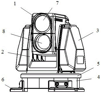
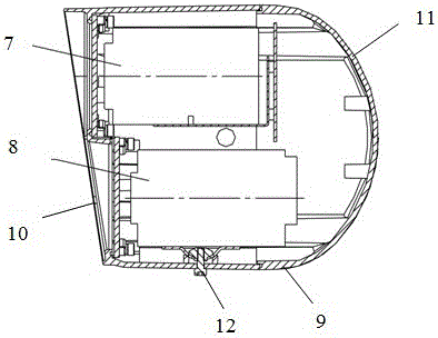
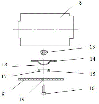
[0034] figure 2 is a side sectional view of the camera of the present invention; image 3 It is an installation explosion diagram of the adjusting mechanism of the present invention; Figure 4 It is the installation structure diagram of the adjustment mechanism of the present invention.

[0035] Reference attached Figure 2-4 The specific structure of the rotation adjustment mechanism of a camera laser light of the present invention will be described in detail.

[0036] A rotation adjustment mechanism for a camera laser light of the present invention, the camera includes a camera 1 for TV monitoring; an electronic movement for controlling the movement of the camera 1; a support frame 2 for supporting and fixing the camera 1; a casing 3 for containi...


PUM


Abstract

The invention discloses a rotating adjustment mechanism for a laser lamp of a video camera. The video camera comprises a camera, an electric movement, a support bracket, a casing, a pan and tilt head, a pan and tilt head cover, a footing of the pan and tilt head, a video camera body with the camera fixedly mounted in an inner cavity, a multi-unit protective shield of the laser lamp, a vertical double-window cover fixed at the front end of the multi-unit protective shield for blocking, as well as a rear-end cover for blocking the rear end of the multi-unit protective shield, wherein the rotating adjustment mechanism is arranged below the laser lamp and comprises a fixing nut, a rotating frame, a supporting block and a fixing bolt which sequentially penetrates through a bolt hole of the multi-unit protective shield, the supporting block, the rotating frame and the fixing nut. The rotating adjustment mechanism for the laser lamp of the video camera is simple in structure and convenient to operate, can rapidly adjust the illumination range of the laser lamp, and provides convenience for an operator to use the video camera at night remotely.

Description

technical field [0001] The invention belongs to a monitoring camera of security equipment, in particular to a rotation adjustment mechanism of a camera laser light for adjusting the rotation angle of the camera laser light. Background technique [0002] At present, the cameras of the closed-circuit television monitoring system are generally divided into indoor units and outdoor units. Structurally, it can be divided into multi-unit cameras and intelligent high-speed dome cameras. Intelligent high-speed dome cameras are divided into wall-mounted (suspension), ceiling-mounted and embedded (ceiling-mounted). Ceiling-mounted and embedded are generally suitable for indoor installations with suspended ceilings. Wall-mounted types are generally suitable for outdoor or indoor environments without Environmental installation of suspended ceilings. The cameras of the closed-circuit television monitoring system can also be divided into fixed-mounted and vehicle-mounted integrated came...

Claims


Application Information

Patent Timeline
Patent Type & Authority Patents(China)
IPC IPC(8): H04N5/225H04N7/18
Inventor 王春宣赵长贺
Owner 深圳市腾隆达智能科技有限公司
Learn More