
Electro-hydraulic fully variable valve drive mechanism

An electronically controlled hydraulic and driving mechanism technology, which is applied in the direction of engine components, machines/engines, mechanical equipment, etc., can solve the problem that the gas distribution phase and valve lift cannot be adjusted reasonably, the valve opening and closing phases cannot be adjusted independently of each other, and the fuel consumption of the engine is affected and other issues, to achieve the effects of kinetic energy recovery, convenient deployment, and simplified structure

Active Publication Date: 2022-02-08
WUXI WEIFU HIGH TECH CO LTD
View PDF5 Cites 0 Cited by
  • Summary
  • Abstract
  • Description
  • Claims
  • Application Information

AI Technical Summary

Problems solved by technology

[0002] At present, the variable phase and variable valve lift mechanism on the vehicle engine is mainly the cam valve lift mechanism, which changes the valve timing and valve lift through the transformation of the cam. This structure can only realize part of the valve with fixed size. Lift adjustment, and the opening and closing phase of the valve cannot be adjusted independently of each other, only early opening and early closing or late opening and late closing can be realized at the same time, therefore, it is impossible to reasonably adjust the valve timing and valve lift required by the engine under different working conditions adjust;
[0003] During the working process of the existing hydraulic valve system, some systems can realize the variable adjustment of valve phase and valve lift, but due to the complex structure of the system and large technical power consumption, it is easy to affect the fuel consumption of the engine

Method used


Image

  • Electro-hydraulic fully variable valve drive mechanism
  • Electro-hydraulic fully variable valve drive mechanism
  • Electro-hydraulic fully variable valve drive mechanism

Examples


Embodiment Construction

[0036] In order to make the object, technical solution and advantages of the present invention more clear, the present invention will be further described in detail below in conjunction with the accompanying drawings and embodiments. It should be understood that the specific embodiments described here are only used to explain the present invention, not to limit the present invention.

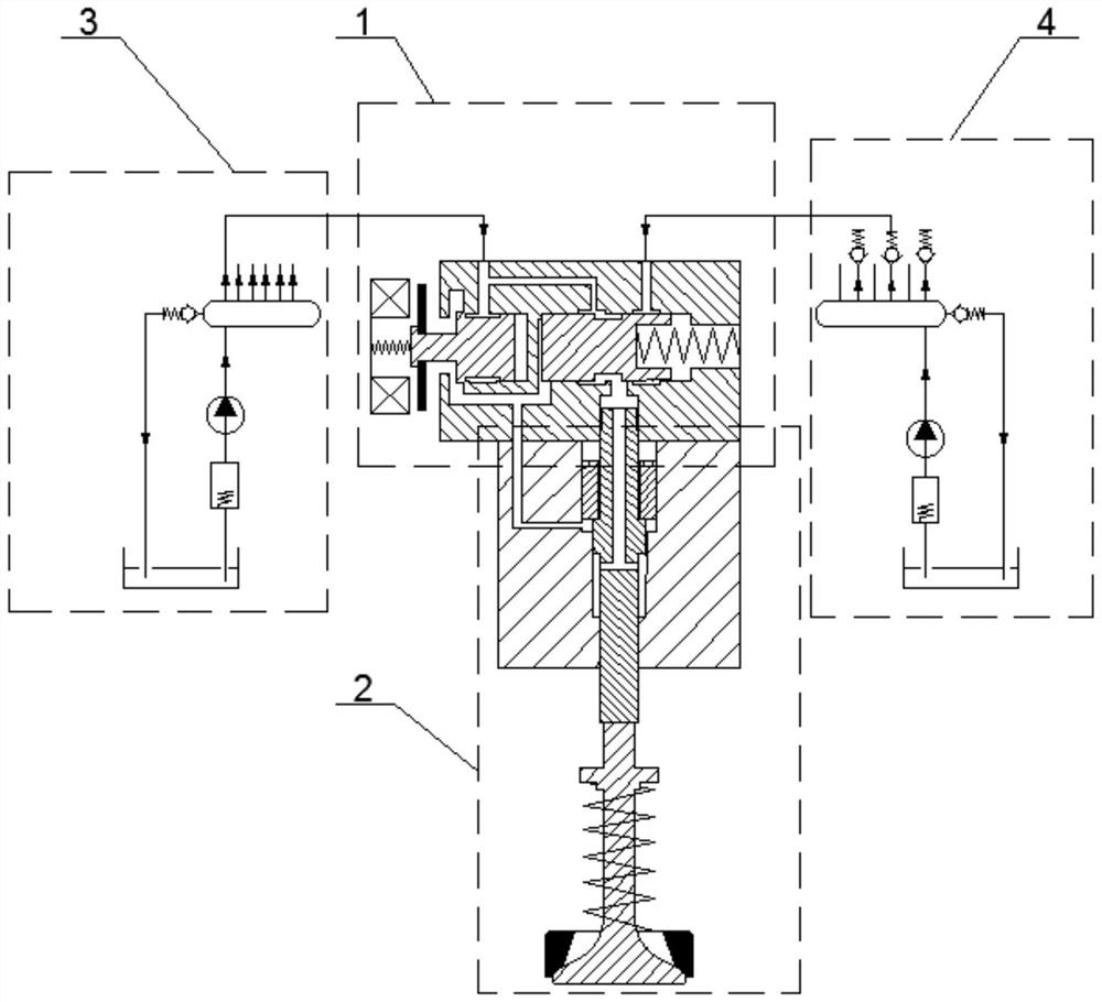
[0037] Please refer to the attached figure 1 , The present invention provides an electronically controlled hydraulic fully variable valve drive mechanism, including a hydraulic drive assembly 1, a valve control assembly 2, a low pressure oil circuit 3, a high pressure oil circuit 4, a valve 5, a valve spring 6 and a valve seat 7.

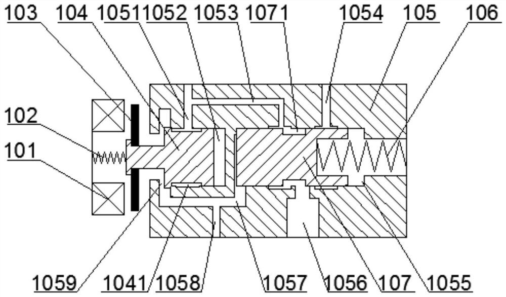
[0038] Please refer to the attached figure 2 , the hydraulic drive assembly 1 includes an electromagnet 101, an armature spring 102, an armature 103, a low-pressure spool 104, a valve body 105 and a high-pressure spool 107;

[0039] One end of the armature spring 1...


PUM


Abstract

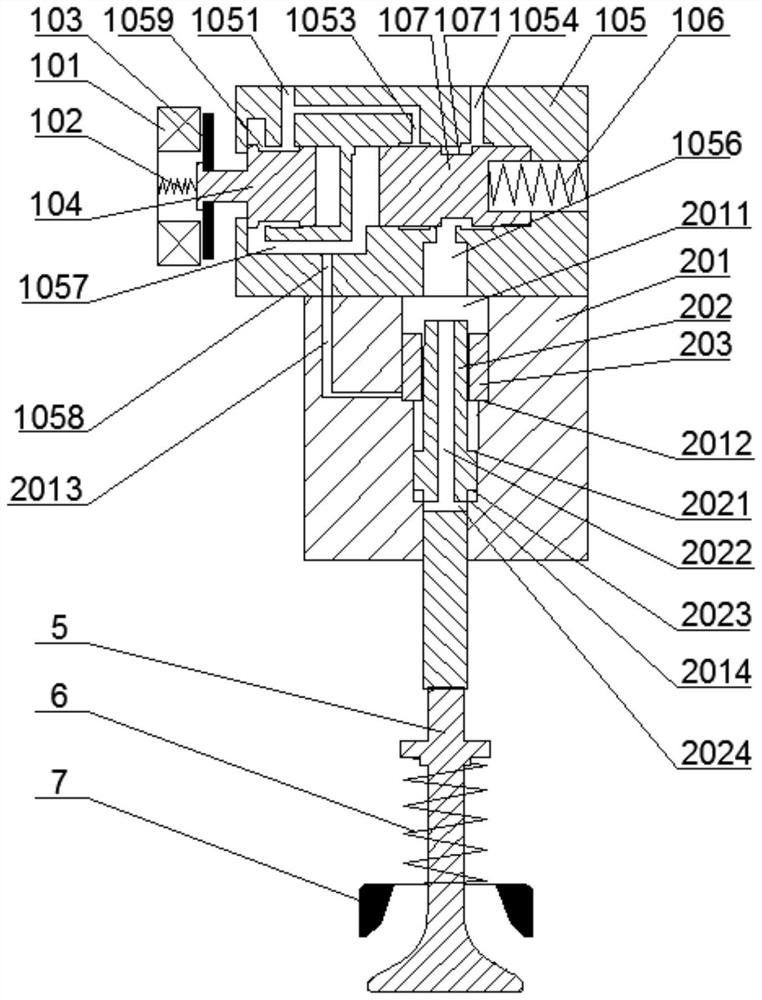
The invention provides an electronically controlled hydraulic fully variable valve drive mechanism, which includes a low-pressure valve core, a valve body, a high-pressure valve core, a cylinder liner and a first piston; the low-pressure valve core is slidably arranged on one side of the valve body; the high-pressure valve core The valve core is slidingly arranged on the other side of the valve body; the valve body is provided with a low-pressure oil chamber that can communicate with the low-pressure oil inlet, and one end of the high-pressure valve core extends into the low-pressure oil chamber; the bottom of the valve body is provided with a pressure oil outlet The valve body is provided with a low-pressure oil channel connected to the low-pressure oil inlet; the other end of the low-pressure oil channel can be connected to the pressure oil outlet; the cylinder liner is arranged at the bottom of the valve body, and the first piston penetrates the cylinder liner; One end of the first piston can extend into the pressure oil outlet. The invention has a compact structure, adopts an electronically controlled hydraulic mode to drive the valve for fully variable opening and closing, reduces technical power consumption, achieves the effects of energy recovery and action buffering, and has a high safety factor.

Description

technical field [0001] The invention relates to the technical field of engines, in particular to an electronically controlled hydraulic fully variable valve driving mechanism. Background technique [0002] At present, the variable phase and variable valve lift mechanism on the vehicle engine is mainly the cam valve lift mechanism, which changes the valve timing and valve lift through the transformation of the cam. This structure can only realize part of the valve with fixed size. Lift adjustment, and the opening and closing phase of the valve cannot be adjusted independently of each other, only early opening and early closing or late opening and late closing can be realized at the same time, therefore, it is impossible to reasonably adjust the valve timing and valve lift required by the engine under different working conditions adjust; [0003] In the working process of the existing hydraulic valve system, some systems can realize variable adjustment of valve phase and valv...

Claims


Application Information

Patent Timeline
Patent Type & Authority Patents(China)
IPC IPC(8): F01L1/344F01L13/00F01L9/10
CPCF01L1/3442F01L13/0015F01L2001/3443
Inventor 王亚伟钱长俊何小川冯利军李刚周俞栋李美娟
Owner WUXI WEIFU HIGH TECH CO LTD
Learn More