Shielding mechanism and its assembly for rainproof and low wind resistance of electric vehicle
A technology of electric vehicles and wind resistance, applied in the field of electric vehicles, can solve problems such as low weight, traffic accidents, and difficult removal of awnings
- Summary
- Abstract
- Description
- Claims
- Application Information
AI Technical Summary
Problems solved by technology
Method used
Image
Examples
Embodiment 1
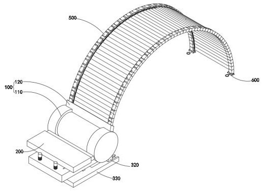
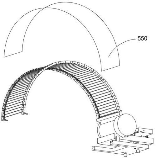
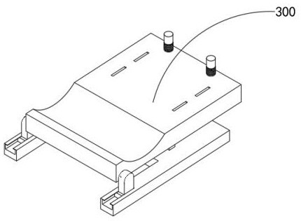
[0051] combine figure 1 , 4 , 6, 7 and 8, the electric vehicle rainproof and low wind resistance shielding mechanism and its assembly provided by the present invention include a protection assembly 100, a limit drive assembly 200, a fixing assembly 300, a restraint mechanism 400, an extension assembly 500 and Engagement mechanism 600, wherein the limit drive assembly 200 is fixedly welded on the protective assembly 100, and the fixed assembly 300 is welded to the bottom of the sealed shell 110 inside the protective assembly 100, while the constraint mechanism 400 is movably installed in the inner cavity of the protective assembly 100, stretching The assembly 500 is wound on the restraining mechanism 400, and in addition, the engaging mechanism 600 is installed at the lower end of the electric vehicle rearview mirror.
[0052] The protection combination 100 includes a sealed casing 110 and a guide 120, the limit drive assembly 200 includes a screw rod 250, a safety slot 210, a...
Embodiment 2
[0057] combine Figure 6 As shown, in the above-mentioned embodiment, by setting the safety groove 210, the overall load of the safety groove 210 is increased. To balance the overall stability of the safety slot 210 and the inner board 220, the limit drive assembly 200 also includes an inner board 220 installed outside the sealed casing 110, a safety slot 210 inserted outside the inner board 220, and a safety slot 210 installed inside the inner board 220. The servomotor 230 and the chain 240 engaged on the drive shaft at the outer end of the servomotor 230.
Embodiment 3
[0059] combine Figure 7 As shown, in the above embodiment, the inner shaft 410 is movably installed in the middle of the inner cavity of the sealed housing 110, and two pads 420 for winding the buckle 510 and the deflector 520 are installed on the inner shaft 410, and at the same time Two gears 430 are installed at both ends of the inner shaft 410, and the fitting and meshing between the gears 430 and the helical end of the screw rod 250 can facilitate the fast retraction and release of the buckle 510 and the deflection member 520. The inner shaft 410 of the inner cavity of the sealing shell 110 , the backing plate 420 installed on the inner shaft 410 and the gear 430 located outside the backing plate 420 , and the gear 430 is installed at both ends of the inner shaft 410 .
PUM
 Abstract
Description
Claims
Application Information
 - R&D
- Intellectual Property
- Life Sciences
- Materials
- Tech Scout
- Unparalleled Data Quality
- Higher Quality Content
- 60% Fewer Hallucinations
Browse by: Latest US Patents, China's latest patents, Technical Efficacy Thesaurus, Application Domain, Technology Topic, Popular Technical Reports.
© 2025 PatSnap. All rights reserved.Legal|Privacy policy|Modern Slavery Act Transparency Statement|Sitemap|About US| Contact US: help@patsnap.com


