Insulation sealing structure of motor stator outgoing line
A technology of insulation sealing and motor stator, applied in the direction of electrical components, electromechanical devices, electric components, etc., can solve the problems of cumbersome wiring process, enlarged junction box volume, and increased occupied space
- Summary
- Abstract
- Description
- Claims
- Application Information
AI Technical Summary
Problems solved by technology
Method used
Image
Examples
no. 1 example
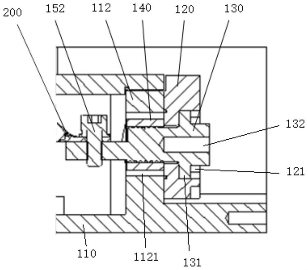
[0031] Such as figure 2 with Image 6 As shown, the mounting hole 121 is a stepped hole, including a first hole 1211 , a second hole 1212 and a stepped surface 1213 connected between the first hole 1211 and the second hole 1212 . The first hole 1211 extends from one side of the wire base to the stepped surface 1213 , and the second hole 1212 extends from the stepped surface 1213 to the other side of the wire base.
[0032] Specifically, the cross-section of the first hole 1211 is larger than the cross-section of the second hole 1212 , so the stepped surface 1213 is formed therebetween. And the size of the first hole 1211 and the second hole 1212 satisfies that the terminal post 130 can pass through, and the cross-sectional shape of the second hole 1212 and the terminal post 130 can be consistent, such as circular or polygonal etc., the polygon includes square, triangle and so on. Wherein, when the cross section of the terminal post 130 is square, the terminal post 130 can ...
no. 2 example
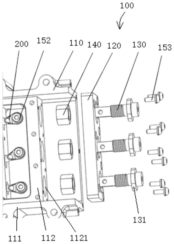
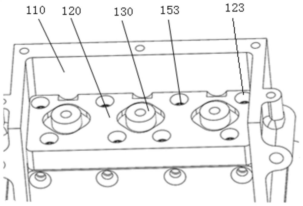
[0039] The difference from the first embodiment is that the terminal post 130 passes through the installation hole 121 , and the outer wall of the terminal post 130 is provided with a baffle plate 131 abutting against the terminal block 120 and covering the installation hole 121 , so as to prevent leakage between the terminal post 130 and the installation hole 121 and the like.
[0040] The terminal post 130 can be screwed and fixed to the installation hole 121 . Of course, the installation hole 121 can also be a through hole, and is locked by the locking member 140 .
no. 3 example
[0042] The difference from the first embodiment is that the terminal post 130 and the terminal seat 120 are integrally formed to avoid the problem of poor sealing caused by the connection between the two.
[0043] Such as Figure 1 to Figure 5As shown, the connection terminal 200 and the locking member 140 are located on the same side of the terminal block 120 , and the external circuit is located at the end of the connection terminal 200 away from the connection terminal 200 .
[0044] Specifically, the external circuit is fixed on the terminal 130 by the first bolt, and the terminal 200 is fixed on the terminal 130 by the second bolt 152 , which is convenient for fixing and simple in structure.
[0045] More specifically, refer to Figure 4 with Figure 5 A first threaded hole 132 is provided at one end of the terminal 130 connected to the external circuit, and a first bolt cooperates with the first threaded hole 132 so that the external circuit is fixed on the terminal 13...
PUM
 Abstract
Description
Claims
Application Information
 - Generate Ideas
- Intellectual Property
- Life Sciences
- Materials
- Tech Scout
- Unparalleled Data Quality
- Higher Quality Content
- 60% Fewer Hallucinations
Browse by: Latest US Patents, China's latest patents, Technical Efficacy Thesaurus, Application Domain, Technology Topic, Popular Technical Reports.
© 2025 PatSnap. All rights reserved.Legal|Privacy policy|Modern Slavery Act Transparency Statement|Sitemap|About US| Contact US: help@patsnap.com


