
Assembly process of oil-free vacuum pump

An oil-free vacuum pump and assembly process technology, which is applied in the direction of assembly machines, manufacturing tools, metal processing equipment, etc., can solve the problems of reducing the installation efficiency of oil-free vacuum pumps, the fixed structure of the cylinder end surface and the fixed deviation of the cylinder, and the easy installation position of the rotor. Problems such as offset

Active Publication Date: 2021-07-30
NANTONG BEIKE VACUUM MACHINERY CO LTD
View PDF7 Cites 0 Cited by
  • Summary
  • Abstract
  • Description
  • Claims
  • Application Information

AI Technical Summary

Problems solved by technology

[0003] In the existing small, medium and micro enterprises, the rotor mostly relies on the percussion hammer to hit the inside of the cylinder. The installation position inside the cylinder is easy to shift, and during the knocking process, the smooth surface at the bottom of the cylinder is easy to touch the force-bearing surface and be damaged, which affects the fixed structure of the end surface of the cylinder. On the other hand, the end surface of the cylinder When the fixed structure is fixed to the cylinder body, in view of the fact that the fixed structure at the end of the cylinder body is easy to adhere to oil stains, the fixed structure at the end of the cylinder body and the cylinder body are prone to slip when the cylinder body is fixed, resulting in the fixed structure of the end surface of the cylinder body It takes a long time to calibrate and position the fixing of the cylinder block, which not only reduces the installation efficiency of the oil-free vacuum pump, but also easily causes deviations in the fixed structure of the end face of the cylinder block and the fixing of the cylinder block, which affects the use effect of the oil-free vacuum pump

Method used


Image

  • Assembly process of oil-free vacuum pump
  • Assembly process of oil-free vacuum pump
  • Assembly process of oil-free vacuum pump

Examples


specific Embodiment approach

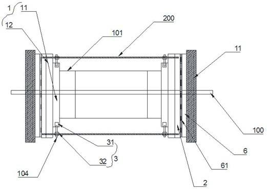
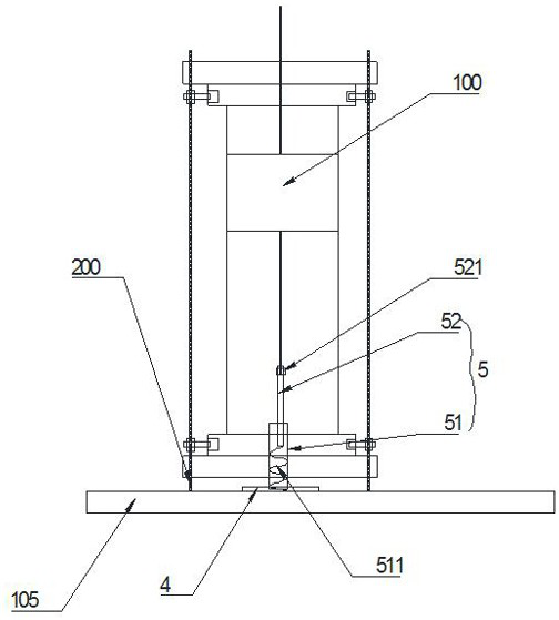
[0027] Such as Figure 1 to Figure 2 A specific embodiment of the present invention specifically includes the following steps:

[0028] S1. The openings at both ends of the cylinder body 101 are fitted with outwardly protruding annular step surfaces 1, and several clamping rods 200 are connected to the two annular step surfaces 1, and several clamping rods 200 surround the outside of the cylinder body 101 in a circular shape. And it is arranged coaxially with the cylinder body 101, and the locking rods 200 all extend outside the annular stepped surface 1;

[0029] S2. Using several clamping rods 200 as suspended force points, knock the rotor 100 evenly inside the cylinder body 101;

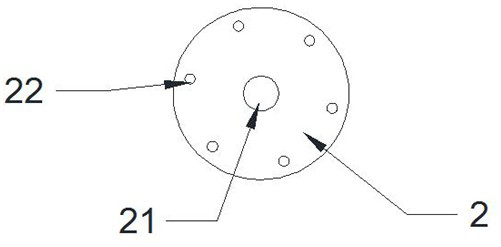
[0030] S3, passing the sulfuric acid paper 2 through the rotor 100 and the clamping rod 200 in sequence and attaching them to the openings at both ends of the cylinder body 101;

[0031] S4. The front cover 102 and the rear cover 103 are pre-positioned against the sulfuric acid paper 2 and fixed...


PUM


Abstract

The invention discloses an assembly process of an oil-free vacuum pump. The assembly process specifically comprises the following steps that S1, opening positions at the two ends of a cylinder body are sleeved with annular step surfaces protruding outwards, a plurality of clamping rods are connected to the two annular step surfaces, the clamping rods are circularly arranged on the outer side of the cylinder body in a surrounding mode and are coaxially arranged with the cylinder body, and the clamping rods extend to the outer sides of the annular step surfaces; S2, the clamping rods are used as suspended stress points, and a rotor is uniformly knocked into the cylinder body; S3, masking paper sequentially penetrates through the rotor and the clamping rods and is attached to openings in the two ends of the cylinder body; and S4, a front cover plate and a rear cover plate are pre-positioned and abut against the masking paper and are fixedly connected with the annular step surfaces. According to the assembly process, the connecting efficiency between the front cover plate or the rear cover plate and the openings of the cylinder body is improved, and the front cover plate or the rear cover plate can be accurately positioned and connected to the openings of the cylinder body.

Description

Technical field: [0001] The invention relates to the technical field of vacuum pump production, in particular to an assembly process of an oil-free vacuum pump. Background technique: [0002] Oil-free vacuum pump is a mechanical vacuum pump that can run without any oil for lubrication. It is composed of stator, rotor, rotary vane, cylinder block, motor and other main parts. The rotor with rotary vanes is installed eccentrically in the cylinder. When the rotor rotates at high speed, the four radially sliding rotary vanes in the rotor groove divide the pump chamber into four working chambers. Due to the centrifugal force, the rotary vanes are close to the The cylinder wall separates the inlet and outlet of the stator, runs in circles, changes the capacity, and discharges the inhaled gas from the exhaust port, so as to achieve the purpose of pumping air. From the working principle of the oil-free vacuum pump, the rotor is inside the cylinder installation is particularly import...

Claims


Application Information

Patent Timeline
IPC IPC(8): B23P21/00
CPCB23P21/00Y02E60/10
Inventor 王旭峰姚新建邓娟
Owner NANTONG BEIKE VACUUM MACHINERY CO LTD
Learn More