
Automatic bundled pipe feeding device for circular sawing machine and feeding method thereof

A technology for automatic feeding and circular sawing machines, which is applied to sawing machine devices, metal sawing equipment, metal processing equipment, etc., and can solve problems such as low work efficiency and inability to realize fully automatic program control

Pending Publication Date: 2021-07-30
卢成奔
View PDF17 Cites 2 Cited by
  • Summary
  • Abstract
  • Description
  • Claims
  • Application Information

AI Technical Summary

Problems solved by technology

The traditional sawing and cutting production line adopts driving loading, or hoists the bundled raw materials to be cut to the feeding table with a crane, and manually distributes the materials. The feeding device transfers the raw materials on the feeding table to the conveying roller before the saw. , the conveying roller table before sawing conveys the raw material to the sawing roller table, the raw material is limited by the baffle plate on the sawing roller table, stops moving forward, the sawing clamping device clamps the material, the saw blade saws the incoming material, and the sawing After the cutting is completed, the cut-to-length material enters the output roller table after sawing and enters the collecting tank. The process of bundling and feeding is manual feeding. The bundled materials are hoisted to the vicinity of the material support frame to loosen, and then the raw materials are placed one by one. It is hoisted from the ground to the material-bearing platform and arranged to cooperate with the next material-moving action. Not to mention the low work efficiency, it also requires the cooperation of multiple people to complete the operation at the same time. At the same time, it is impossible to realize the automatic program control of the whole process, and thus has Need to make improvements

Method used


Image

  • Automatic bundled pipe feeding device for circular sawing machine and feeding method thereof
  • Automatic bundled pipe feeding device for circular sawing machine and feeding method thereof
  • Automatic bundled pipe feeding device for circular sawing machine and feeding method thereof

Examples


Embodiment Construction

[0036] The following will clearly and completely describe the technical solutions in the embodiments of the present invention with reference to the accompanying drawings in the embodiments of the present invention. Obviously, the described embodiments are only some, not all, embodiments of the present invention. Based on the embodiments of the present invention, all other embodiments obtained by persons of ordinary skill in the art without creative efforts fall within the protection scope of the present invention.

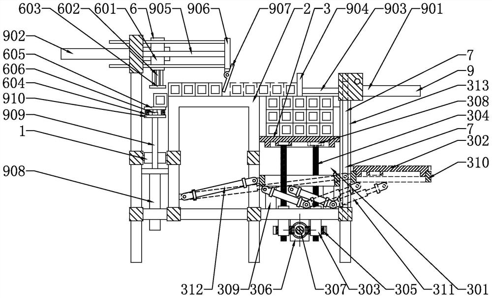
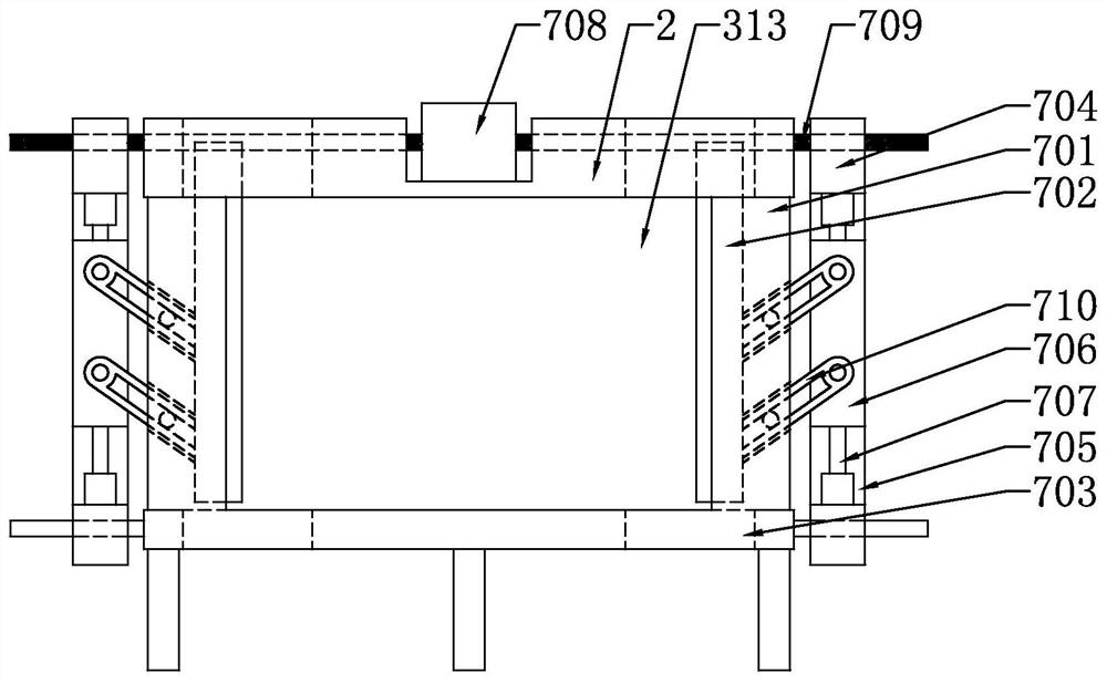
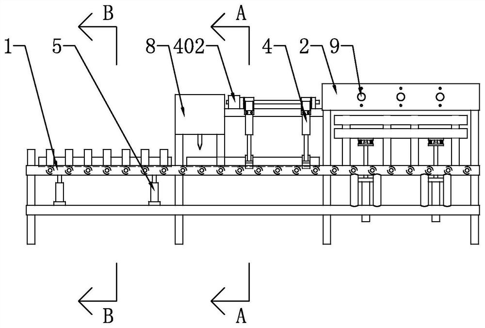
[0037] Such as Figure 1-Figure 5 As shown, the present invention discloses an automatic feeding device for bundled pipes for a circular saw machine and a feeding method thereof, including a frame 2 with a sawing roller table 1, and a cutting device arranged above the sawing roller table 1 8. In a specific embodiment of the present invention: a lifting device 3 for lifting pipes is installed on the frame 2, a material distribution device 9 is installed on the frame...


PUM


Abstract

The invention relates to an automatic bundled pipe feeding device for a circular sawing machine and a feeding method thereof. The automatic bundled pipe feeding device comprises a rack with a sawing roller way, wherein a lifting device used for lifting a pipe, a material distributing device installed on the rack and used for feeding the pipe into a saw cutting roller way, a saw cutting clamping device installed on the rack and used for clamping and lifting the pipe on the saw cutting roller way to be cut by cutting equipment and a discharging device installed on the rack and used for discharging the pipe cut by the cutting equipment out of the saw cutting roller way are installed on the rack. A worker lifts the bundled pipes to the lifting device through a crane, the lifting device is started, the bundled pipes are lifted to the working position of the material distributing device, the material distributing device is started, the bundled pipes are separated into independent pipes one by one, the pipes are sequentially fed into the saw cutting roller way, the saw cutting clamping device clamps the pipes and moves the pipes to the cutting equipment for cutting, then the pipes sawn by the cutting equipment are put back to the saw cutting roller way, and the discharging device is started to discharge the pipes out of the saw cutting roller way.

Description

technical field [0001] The invention relates to the technical field of cutting equipment, in particular to an automatic feeding device for bundled pipes for a circular saw machine and a feeding method thereof. Background technique [0002] A circular saw is a device primarily used for cutting pipes, bars, and other elongated metal workpieces. The traditional sawing and cutting production line adopts driving loading, or hoists the bundled raw materials to be cut to the feeding table with a crane, and manually distributes the materials. The feeding device transfers the raw materials on the feeding table to the conveying roller before the saw. , the conveying roller table before sawing conveys the raw material to the sawing roller table, the raw material is limited by the baffle plate on the sawing roller table, stops moving forward, the sawing clamping device clamps the material, the saw blade saws the incoming material, and the sawing After the cutting is completed, the cut-...

Claims


Application Information

Patent Timeline
IPC IPC(8): B23D47/04B23D47/00
CPCB23D47/042B23D47/04B23D47/00B23D47/045Y02P70/10
Inventor 不公告发明人
Owner 卢成奔
Learn More