
Automobile lamp mounting foot structure

A technology for automotive lamps and mounting feet, which is applied in signal devices, vehicle parts, transportation and packaging, etc., which can solve the problems of long adjustment period, failure to adjust qualified, large deformation of shell injection molding, etc.

Active Publication Date: 2021-07-27
CHERY AUTOMOBILE CO LTD
View PDF11 Cites 0 Cited by
  • Summary
  • Abstract
  • Description
  • Claims
  • Application Information

AI Technical Summary

Problems solved by technology

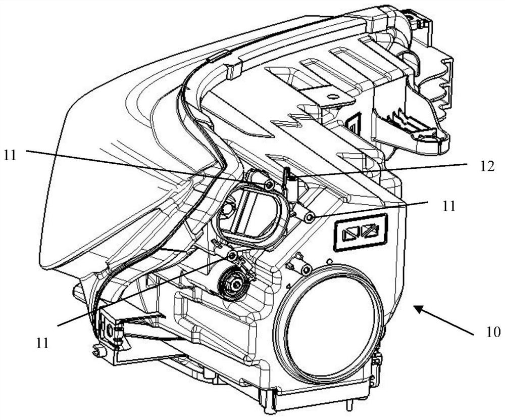
Under normal circumstances, the mounting feet of the lamps are directly injection molded on the lamp shell, and the positioning point with the body fender is often designed on the farthest mounting feet closest to the sheet metal. However, due to the large size of the shell, the mounting feet It is also distributed at the farthest end of the shell, and the shell is a thin-walled part. Adding glass fiber to increase the material strength will make the shell injection deformation larger, resulting in a gap between the lamp and the body sheet metal and surrounding fittings. The surface difference cannot meet the design requirements, affect the appearance quality of the vehicle, and even cause the mounting holes and positioning points to deviate, resulting in failure to install
Based on this situation, engineers can only use other alternative solutions, such as forcing the positioning point on the remote mounting foot as the reference point, and modifying the other parts by matching and verifying the deviation between other parts of the lamp and the mounting point. The position and installation point, this kind of headache and doctor’s foot method will make the matching difficult, the adjustment cycle will be long, and even some points cannot be adjusted due to the large amount of adjustment.

Method used


Image

  • Automobile lamp mounting foot structure
  • Automobile lamp mounting foot structure
  • Automobile lamp mounting foot structure

Examples


Embodiment Construction

[0014] Combine below Figure 1-Figure 8 The present invention is discussed in further detail.

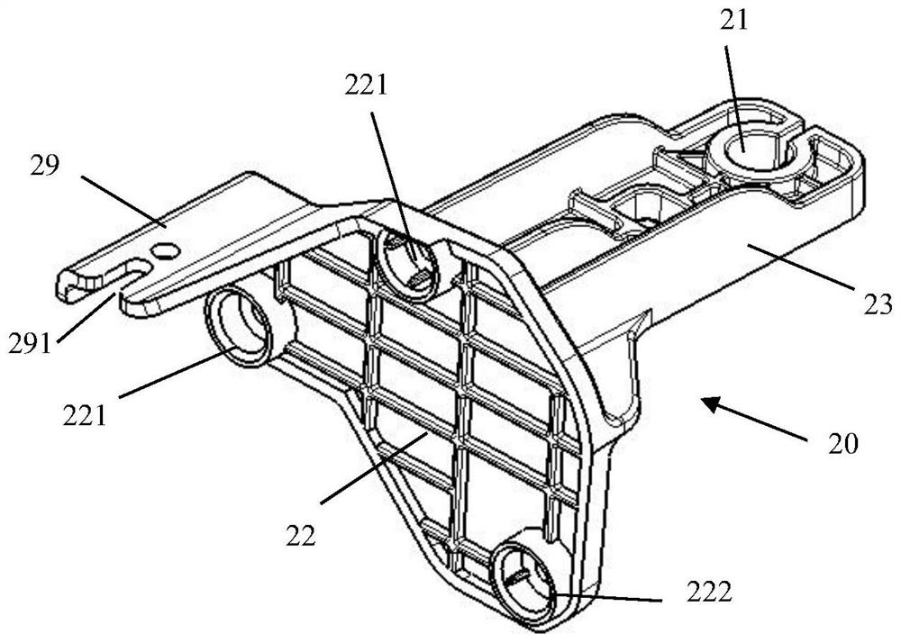
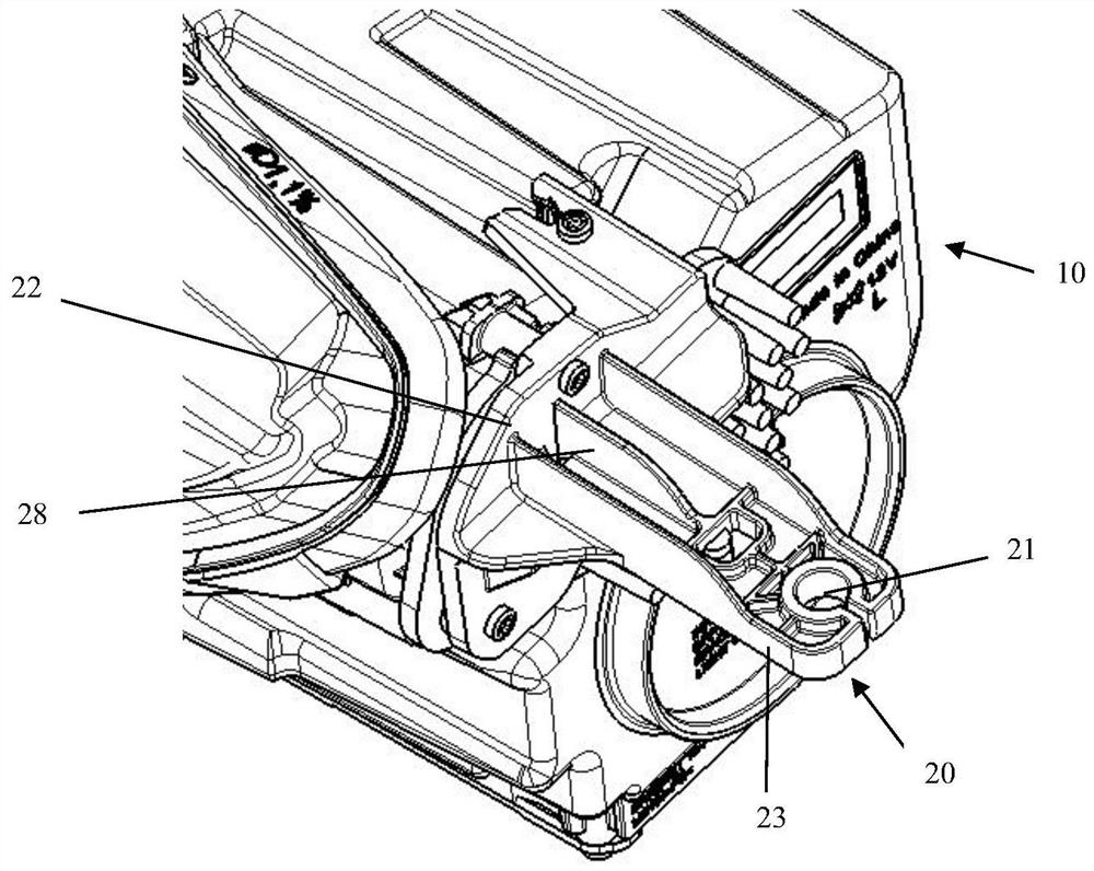
[0015] An automobile lamp mounting foot structure, comprising a lamp housing 10, a mounting foot 20 is provided at the connection position between the lamp housing 10 and the vehicle body sheet metal A, the mounting foot 20 forms a detachable connection with the lamp housing 10, and the mounting foot 20 A threaded hole 21 is opened on the top, and the bolt 30 passes through the threaded hole 21 to fix the mounting foot 20 and the body sheet A. The mounting foot 20 and the lamp housing 10 are made into separate parts, and injection molding is carried out independently. The process is simple, and the deformation of the two parts is small, thereby ensuring the clearance between the lamp and the body sheet metal and the surrounding fittings. Even if the deformation of the lamp housing is relatively large, the mounting feet 20 can be adjusted to achieve adjustment, installation and matc...


PUM


Abstract

The invention aims to provide an automobile lamp mounting foot structure capable of ensuring the clearance and the surface difference between a lamp and an automobile body metal plate as well as between the lamp and peripheral fitting parts. The automobile lamp mounting foot structure comprises a lamp shell, mounting feet are arranged at the connecting position of the lamp shell and the automobile body metal plate, and the mounting feet are detachably connected with the lamp shell. Threaded holes are formed in the mounting feet, and bolts penetrate through the threaded holes to fixedly connect the mounting feet with the automobile body metal plate. According to the scheme, the mounting feet and the lamp shell are manufactured into separated parts, injection molding is independently carried out, the process is simple, the deformation of the two parts is small, then the matching gap and surface difference between the lamp and the automobile body metal plate and between the lamp and peripheral matching parts are guaranteed, and even if the deformation of the lamp shell is large, the lamp shell can be conveniently assembled and disassembled by adjusting the mounting feet, and adjustment, installation and matching are achieved under the condition that the shell is not changed.

Description

technical field [0001] The invention relates to the technical field of automobile lamps, in particular to a mounting foot structure for automobile lamps. Background technique [0002] Because of its practicality and aesthetics, car lights are becoming more and more important in the car body. In order to ensure the firm and reliable installation of car lights, mounting feet are usually provided on the car light housing, and the mounting feet correspond to the car body. position installed together. Under normal circumstances, the mounting feet of the lamps are directly injection molded on the lamp shell, and the positioning point with the body fender is often designed on the farthest mounting feet closest to the sheet metal. However, due to the large size of the shell, the mounting feet It is also distributed at the farthest end of the shell, and the shell is a thin-walled part. Adding glass fiber to increase the material strength will make the shell injection deformation lar...

Claims


Application Information

Patent Timeline
Patent Type & Authority Applications(China)
IPC IPC(8): B60Q1/00
CPCB60Q1/00Y02T10/40
Inventor 郑超群肖星徐青王存峰
Owner CHERY AUTOMOBILE CO LTD
Learn More