
Rail robot

A track robot and track technology, applied in the field of robots, can solve the problem of low motion accuracy and achieve the effect of improving motion accuracy

Pending Publication Date: 2021-07-27
INNER MONGOLIA JINGNENG KANGBASHI THERMAL POWER CO LTD +1
View PDF0 Cites 0 Cited by
  • Summary
  • Abstract
  • Description
  • Claims
  • Application Information

AI Technical Summary

Problems solved by technology

[0004] The main purpose of the present invention is to provide an orbital robot to solve the technical problem that the orbital robot in the prior art has low motion accuracy due to unreasonable drive wheel settings

Method used


Image

  • Rail robot
  • Rail robot

Examples


Embodiment Construction

[0020] It should be noted that, in the case of no conflict, the embodiments of the present invention and the features in the embodiments can be combined with each other. The present invention will be described in detail below with reference to the accompanying drawings and examples.

[0021] In order to enable those skilled in the art to better understand the solutions of the present invention, the following will clearly and completely describe the technical solutions in the embodiments of the present invention in conjunction with the drawings in the embodiments of the present invention. Obviously, the described embodiments are only It is an embodiment of a part of the present invention, but not all embodiments. Based on the embodiments of the present invention, all other embodiments obtained by persons of ordinary skill in the art without making creative efforts shall fall within the protection scope of the present invention.

[0022] It should be noted that the terms "first...


PUM


Abstract

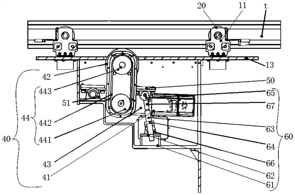
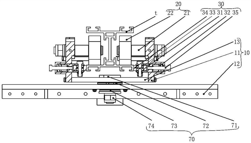
The invention provides a rail robot. The rail robot is characterized in that a bearing guide wheel mechanism and a limiting guide wheel mechanism are arranged on a bearing main body; a rotating shaft of the bearing guide wheel mechanism is arranged in the horizontal direction, the limiting guide wheel mechanism is located on the lower side of the bearing guide wheel mechanism, and a rotating shaft of the limiting guide wheel mechanism is arranged in the vertical direction; a driving wheel mechanism is arranged on the bearing main body; and a rotating shaft of the driving wheel mechanism is arranged in the horizontal direction. The bearing guide wheel mechanism mainly bears the weight of the rail robot, and the limiting guide wheel mechanism can play a role in limiting and guiding the movement of the rail robot. In addition, the additionally-arranged driving wheel mechanism directly abuts against and is matched with the bottom face of a rail to drive the bearing main body to move on the rail, and the driving wheel mechanism does not need to bear the gravity load of the rail robot, so that the influence of other factors on the driving wheel mechanism can be reduced, and the motion precision of the rail robot is improved.

Description

technical field [0001] The present invention relates to the technical field of robots, in particular to an orbital robot. Background technique [0002] As the application of robots becomes more and more extensive, in the occasions that have certain requirements for safety, more and more robots that walk along the track will be used to improve the reliability of equipment movement. At present, most orbital robots use the mounting method to mount the main structure on the track, mainly relying on the top wheel and side wheel of the orbital robot to make rolling contact with the top and side of the track respectively. [0003] In the above structure, one of the top wheel or the side wheel will be selected as the driving wheel. In actual use, since the above-mentioned top wheel or side wheel will bear the weight of the orbital robot or maintain the operation of the orbital robot, if the above-mentioned top wheel or side wheel is used as a driving wheel, the motor will need to b...

Claims


Application Information

Patent Timeline
IPC IPC(8): B25J5/02B25J5/00B25J19/00
CPCB25J5/007B25J5/02B25J19/00
Inventor 刘炜郝晓斌王微王立平董曙君张博李晓莹潘伟民
Owner INNER MONGOLIA JINGNENG KANGBASHI THERMAL POWER CO LTD
Learn More