A layered liquid pipetting device and method of use thereof

A liquid pipetting device and liquid pipetting technology, applied in chemical instruments and methods, measuring tubes/pipettes, laboratory containers, etc., can solve the problems of reducing the accuracy of pipetting, reducing the purity of pipetting liquids, etc., and achieve improved The effect of pipetting accuracy, reducing the requirements for experience and quality, and reducing the risk of absorbing the lower layer of liquid

Active Publication Date: 2022-05-24
臻叶生物科技有限公司
View PDF9 Cites 0 Cited by
  • Summary
  • Abstract
  • Description
  • Claims
  • Application Information

AI Technical Summary

Problems solved by technology

[0004] like image 3 As shown, because the liquid suction port 2-2 is directly facing the layer C liquid under the layer B liquid, when sucking the layer B liquid, especially when the layer B liquid is relatively shallow, it is very easy to directly place the C layer under the layer B liquid. The layer of liquid is sucked away together, resulting in a reduction in the purity of the pipetted liquid, which also reduces the pipetting accuracy
[0005] Moreover, because when pipetting, the staff needs to hold the test tube 1 with one hand and squeeze or release the squeeze pack 2-1 with the other hand, so the experience and quality requirements of the staff are relatively high, and the staff needs to be highly concentrated Keep your hands steady. Once the staff accidentally inserts the lower end of the pipette 2 into the layer C liquid below the B layer liquid, it is easy to directly suck away the C layer liquid below the B layer liquid. Also reduces pipetting accuracy

Method used


Image

  • A layered liquid pipetting device and method of use thereof
  • A layered liquid pipetting device and method of use thereof
  • A layered liquid pipetting device and method of use thereof

Examples


Embodiment 1

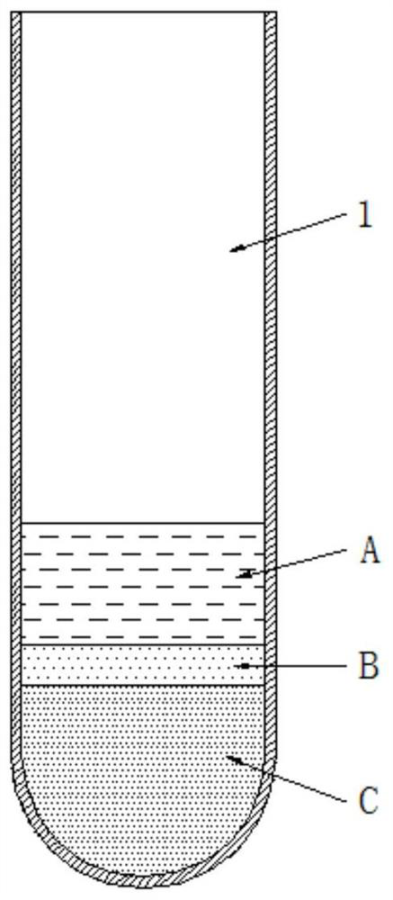
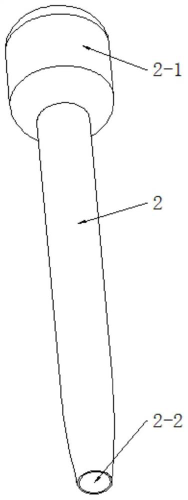
[0070] A layered liquid pipetting device consisting of pipette 2 and pipette holder.

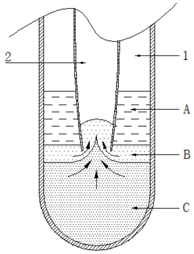
[0071] as Figure 4 As shown, the upper end of the pipette 2 is provided with a squeeze pack 2-1, and the lower end side wall of the pipette 2 is provided with a suction port 2-2. as Figure 5 As shown, when using a pipette 2 to aspirate liquid, first squeeze squeeze pack 2-1, so that the air inside the pipette 2 is discharged from the suction port 2-2; and then release the squeeze of the squeeze pack 2-1, in the process of loosening the squeeze package 2-1, the inner cavity of pipette 2 can be sucked into the pipette 2 from the suction port 2-2 because it is a negative pressure state.

[0072] as Figure 6-8 As shown, the pipette includes a pipette 3, a pipetting clip 5, a pipetting drive, a lift, a container disc 6, a container holder 7, a container drive.

[0073] as Figure 9 As shown, pipette 3 is provided with pipette placement wells 3-1 and pipette placement wells 3-1 for placing pipettes 2. ...

Embodiment 2

[0093] Example 2 is based on Example 1, the structure of the pipette 2 is improved.

[0094] asFigure 10-12 As shown, in the present embodiment, the lower end of the pipette 2 employs a flat tube 2-3, the flat tube 2-3 has two side walls, respectively, denoted as side wall a and side wall b, at least one side wall is provided with the aspiration port 2-2. as Figure 10 As shown, only the side wall a is provided with a suction port 2-2; as shown Figure 11 and Figure 12 As shown, when both sidewall a and sidewall b are provided with aspiration ports 2-2, the aspirate ports 2-2 on sidewall a are disposed on the posterior side of sidewall a, and the aspiration port 2-2 on sidewall b is disposed in front of side wall b, so that the aspiration port 2-2 on side wall a and the suction port 2-2 on side wall b are set away from each other.

[0095] When only the side wall a is provided with a suction port 2-2, the container needs to be rotated 360° to complete the pipetting.

[0096] When bo...

Embodiment 3

[0100] Example 3 of the present embodiment provides another pipette structure based on Example 2.

[0101] as Figure 13 or Figure 14 As shown, in the present embodiment, the lower end of the flat tube 2-3 is open 2-3-1, the open 2-3-1 is communicated with the aspiration port 2-2.

[0102] By opening the lower end of the flat tube 2-3 to 2-3-1, it is convenient to open the suction port 2-2, making the processing simple and conducive to improving the processing efficiency.

[0103] In the present embodiment, although the lower end of the flat tube 2-3 is open 2-3-1, but because it is a flat tube 2-3, so the lower end of the flat tube 2-3 open 2-3-1 is narrow, when removing the B layer liquid, can reduce the removal of the C layer liquid, compared with the background technique, or can reduce the removal of the C layer liquid, is conducive to improving the removal accuracy, and then conducive to improving the experimental accuracy.


PUM


Abstract

The invention discloses a layered liquid pipetting device and a method for using the same. The device includes a pipette and a pipette rack. The upper end of the pipette is provided with a squeeze bag, and the side wall of the lower end of the pipette is provided with a liquid suction port. The pipetting rack includes a pipetting tray, which is provided with a pipette placement hole, and the upper surface of the pipetting tray is provided with a pipetting clip for squeezing the squeeze pack and a pipetting clip for driving the pipetting clip to perform the extrusion action. The liquid driving part, the pipetting tray is connected with the container tray through the lifting part, and the upper end surface of the container tray is provided with a container seat for holding the container and a container driving part for driving the container seat to rotate. Method: Insert the pipette into the pipette placement hole, the pipette driver drives the pipette clip to squeeze the squeeze bag; place the container on the container seat, lower the pipette tray, and make the suction port enter the layered liquid In the layer of liquid to be removed; the pipetting clamp releases the squeeze on the squeeze bag, and the container driver drives the container seat to rotate, so that the liquid suction port absorbs the layer of liquid to be removed in the layered liquid. The invention can improve the liquid pipetting precision.

Description

Technical field [0001] The present invention relates to the technical field of layered liquid separation tools, in particular a layered liquid pipetting device and a method of use thereof. Background [0002] In biological, medical, and chemical experiments, the characteristics of different densities between substances are often used to separate each component by means of density gradient centrifugation. When it is necessary to remove the liquid to be removed in the layer of the layer of liquid in the container, for example, when it is necessary to remove such as Figure 1 When the layer B liquid in the layered liquid in tube 1 shown, pipette 2 needs to be inserted into the layer B liquid for aspirate. [0003] as Figure 2 As shown, the existing pipette 2 is a round tubular structure, the upper end of the pipette 2 is provided with an extrusion package 2-1, the lower end of the pipette 2 is a circular open, this circular open is the pipette 2-2 of the pipette 2. When using pipette...

Claims


Application Information

Patent Timeline
Patent Type & Authority Patents(China)
IPC IPC(8): B01L3/02
CPCB01L3/021
Inventor 李国良
Owner 臻叶生物科技有限公司
Why Eureka
Try Eureka