Clinical adjustable limb positioning mechanism for orthopedics department

A positioning mechanism and adjustable technology, applied in application, dentistry, dental chairs, etc., can solve the problems that affect the effect of instrument inspection, unfavorable recovery of orthopedic patients, and adjust the positioning position of limbs, so as to improve the recovery efficiency and benefit the legs Restoration and reduction of contact area

Inactive Publication Date: 2021-07-27
李秀玲
View PDF0 Cites 1 Cited by
  • Summary
  • Abstract
  • Description
  • Claims
  • Application Information

AI Technical Summary

Problems solved by technology

[0002] Orthopedics is one of the most common departments in major hospitals. It mainly studies the anatomy, physiology and pathology of the musculoskeletal system, and uses drugs, surgery and physical methods to maintain and develop the normal shape and function of this system. The positioning mechanism is used to position and fix the patient's leg to facilitate subsequent orthopedic examinations. However, when positioning the patient's leg at present, the patient's leg is lifted or supported, which cannot be accurately limited and fixed, causing the patient's leg to shake. It affects the effect of instrument inspection, and the current positioning mechanism cannot adjust the positioning position of the limbs according to the length of the legs of different patients and the inspection position, and fix the same position, which makes the covered position inconvenient for subsequent inspections. Poor comfort during orthopedic surgery is not conducive to the subsequent recovery of orthopedic patients. In view of this, we propose an adjustable limb positioning mechanism for orthopedic clinical use.

Method used


Image

  • Clinical adjustable limb positioning mechanism for orthopedics department
  • Clinical adjustable limb positioning mechanism for orthopedics department
  • Clinical adjustable limb positioning mechanism for orthopedics department

Examples


Embodiment 1

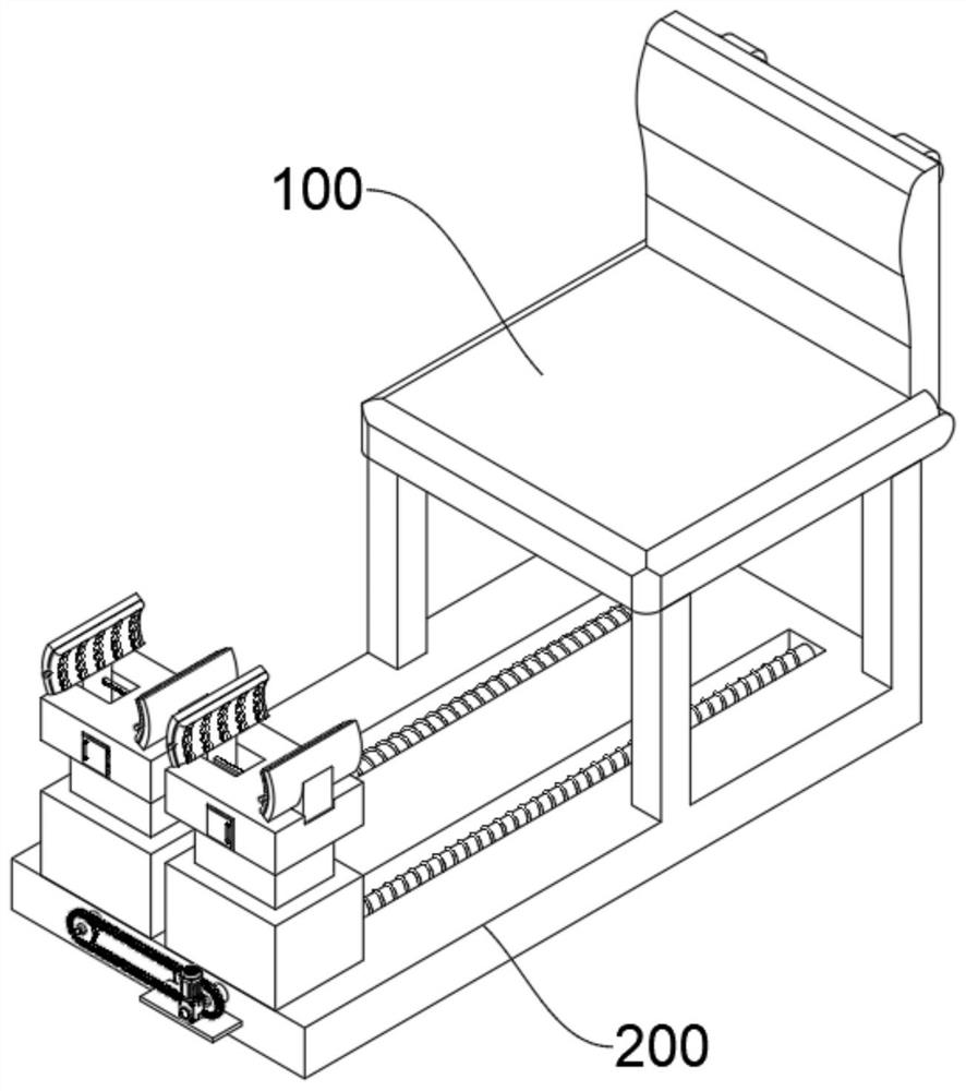
[0044] see Figure 1-Figure 6 As shown, this embodiment provides an adjustable limb positioning mechanism for orthopedic clinical use, including a seat board 100 and a limb positioning device 200 below the seat board 100, and the bottom of the seat board 100 is provided with supporting legs 110 near the four corners, so that the limbs can be positioned The device 200 includes at least:

[0045] The support plate 210, the end of the support leg 110 is fixed directly above the end of the support plate 210, the top of the support plate 210 is provided with two symmetrical transmission grooves 211, the transmission groove 211 is internally rotated and provided with a transmission screw rod 212, two transmission The ends of the screw mandrels 212 are rotated and extend out of the transmission groove 211, and the inside is fixedly connected with a gear plate 213. The two gear plates 213 drive the two gear plates 213 to rotate at the same time through the transmission mechanism. The ...

Embodiment 2

[0051] In order to blow the hot air carrying the medicinal effect on the patient's legs, promote blood circulation, and improve the recovery efficiency of the legs, the difference between this embodiment and Embodiment 1 is that please refer to Figure 7-Figure 9 shown, where:

[0052] A fumigation box 224 is embedded inside the storage box 222, and the outer wall of the fumigation box 224 is connected with two symmetrical transmission pipes 2232. The hole 2231, the inside of the through hole 2231 communicates with the inside of the adjustment plate 223, can fill the inside of the fumigation box 224 with medicinal materials for promoting blood circulation and removing blood stasis, and the electric heating network in the inner layer of the fumigation box 224 is energized and heated, so that the medicinal properties of the medicinal materials flow away with the hot air, and the hot air flows from both sides. The interior of each delivery tube 2232 is transported to the inside o...

Embodiment 3

[0056] In order to make the airbag cushion 2233 stick to the skin of the patient's leg along with the clamping arc plate 2230, and avoid the damage to the patient's leg caused by the rigid impact of clamping, the difference between this embodiment and Embodiment 1 is that, please refer to Figure 10 shown, where:

[0057] The inner surface of the clamping arc plate 2230 is provided with an airbag cushion 2233, and the surface of the airbag cushion 2233 is provided with a plurality of ventilation holes 2234 at equal intervals. The plurality of ventilation holes 2234 correspond to the plurality of through holes 2231 respectively. The airbag cushion 2231 is discharged through a plurality of vent holes 2234 to fumigate the patient's legs, so that the airbag cushion 2233 does not affect the fumigation of hot air. The clamping arc plate 2230 fits the skin of the patient's leg to avoid damage to the patient's leg caused by the rigid impact of the clamping. At the same time, multiple ...


PUM


Abstract

The invention relates to the technical field of limb positioning, and in particular relates to a clinical adjustable limb positioning mechanism for the orthopedics department. The limb positioning mechanism comprises a seat plate and a limb positioning device body below the seat plate, the limb positioning device body at least comprises a supporting plate, two symmetrical conveying grooves are formed in the top of the supporting plate, conveying lead screws and two symmetrical adjusting and limiting devices are rotationally arranged in the conveying grooves, and the adjusting and limiting devices comprise lifting tables; conveying plates are arranged at the bottoms of the lifting tables, the surfaces of the two conveying plates are in threaded fit connection with the outer walls of the two conveying lead screws correspondingly, a containing box is arranged at the top of each lifting table, two symmetrical adjusting grooves are formed in the top of each containing box, two symmetrical adjusting plates are slidably arranged in the two adjusting grooves correspondingly, and clamping arc plates are fixedly connected with the tops of the adjusting plates. According to the invention, the limb positioning position can be conveniently adjusted, legs can be conveniently limited and fixed, the legs can be clamped and fumigated, and the recovery efficiency is improved.

Description

technical field [0001] The invention relates to the technical field of limb positioning, in particular to an adjustable limb positioning mechanism for clinical orthopedics. Background technique [0002] Orthopedics is one of the most common departments in major hospitals. It mainly studies the anatomy, physiology and pathology of the musculoskeletal system, and uses drugs, surgery and physical methods to maintain and develop the normal shape and function of this system. The positioning mechanism is used to position and fix the patient's leg to facilitate subsequent orthopedic examinations. However, when positioning the patient's leg at present, the patient's leg is lifted or supported, which cannot be accurately limited and fixed, causing the patient's leg to shake. It affects the effect of instrument inspection, and the current positioning mechanism cannot adjust the positioning position of the limbs according to the length of the legs of different patients and the inspecti...

Claims


Application Information

Patent Timeline
Patent Type & Authority Applications(China)
IPC IPC(8): A61G15/04A61G15/10A61G15/12A61H33/06A61M37/00
CPCA61G15/007A61G15/02A61G15/10A61G15/12A61G2210/10A61H33/06A61H2033/061A61H2033/068A61H2201/0149A61H2201/0207A61H2201/105A61H2201/1642A61H2205/10A61M37/00A61M2037/0007A61M2205/36A61M2210/086A61M2210/005
Inventor 李秀玲
Owner 李秀玲
Why Eureka
Try Eureka