Shock-resistant base of manipulator

A manipulator, No. 1 technology, applied in mechanical equipment, engine components, springs/shock absorbers, etc., can solve problems such as poor anti-seismic effect of manipulators, and achieve low cost, reduced service life, and strong practicability

Active Publication Date: 2021-07-23
HANGZHOU VOCATIONAL & TECHN COLLEGE
View PDF7 Cites 4 Cited by
  • Summary
  • Abstract
  • Description
  • Claims
  • Application Information

AI Technical Summary

Problems solved by technology

[0006] In order to make up for the deficiencies of the prior art and solve the problem of poor anti-seismic effect of the manipulator, the invention provides a manipulator anti-seismic base

Method used


Image

  • Shock-resistant base of manipulator
  • Shock-resistant base of manipulator
  • Shock-resistant base of manipulator

Examples


Embodiment 1

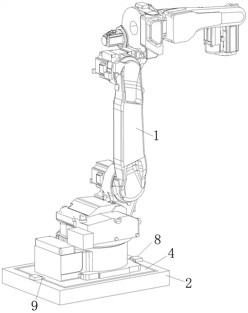
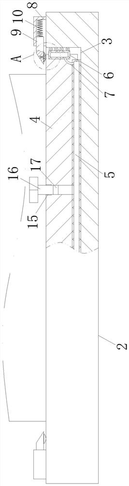
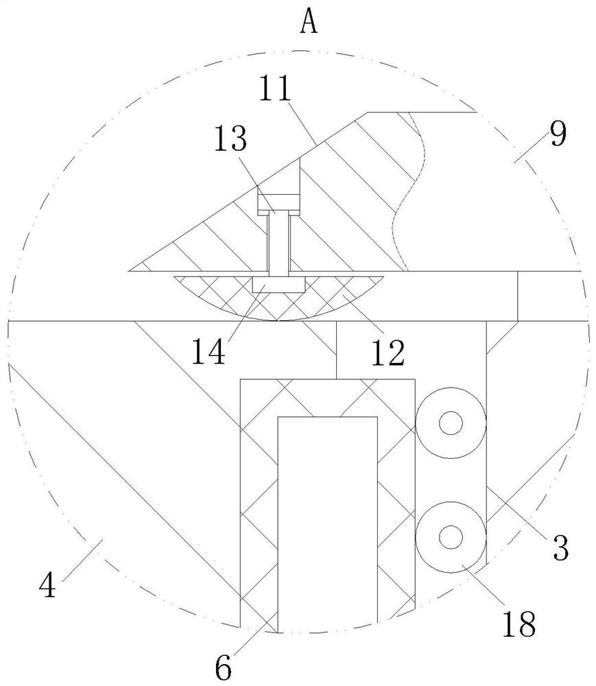
[0030] see Figure 1-5 As shown, a manipulator anti-seismic base according to the present invention includes a manipulator body 1 and a base 2; The mounting plate 4, the bottom end of the mounting plate 4 is provided with a No. 1 buffer bag 5, and the side walls of the mounting plate 4 are respectively provided with a No. 2 buffer bag 6, and the side wall of the No. 2 buffer bag 6 is connected to the installation cavity. There is a gap reserved between the side walls of 3, the No. 1 buffer bag 5 and the No. 2 buffer bag 6 are respectively connected through connecting pipes 7, and the No. 1 buffer bag 5 is connected between the installation plate 4 and the installation cavity 3 The internal gas can be pressed into the No. 2 buffer bag 6 under the extrusion of the No. 2 buffer bag 6, and the No. 2 buffer bag 6 is expanded to fit with the side wall of the installation cavity 3; during work, the base 2 in the prior art passes through The complex electric structure and the install...

Embodiment 2

[0040] see Image 6 As shown, the support ring 19 is provided with a feed port 30 on the side wall corresponding to the air outlet groove 20, the feed port 30 is provided with a blocking block 31, and the support ring 19 at the feed port 30 is There is an elastic net 32 ​​that can wrap and squeeze the blocking block 31; during operation, when the rotating column 18 is working, the blocking block 31 can block the feed port 30 under the pressure of the elastic net 32, thereby The lubricating oil inside the support ring 19 can be preserved to reduce the outflow of the lubricating oil inside the support ring 19 when it is rotating. When the feed port 30 is opened, the lubricating oil can be replenished to the inside of the support ring 19, making the replenishment of the lubricating oil in the rotating column 18 more convenient and quick.

[0041]Working principle: Insert the mounting plate 4 at the bottom of the manipulator into the installation cavity 3, and the opening of the ...


PUM


Abstract

The invention relates to the technical field of manipulator mounting equipment, in particular to a shock-resistant base of a manipulator. The shock-resistant base comprises a manipulator body and a base body, wherein a mounting cavity is formed in the top surface of the base body; a mounting plate matched with the mounting cavity is arranged at the bottom end of the manipulator body; a No. 1 buffering bag is arranged at the bottom end of the mounting plate; No. 2 buffering bags are arranged on the side walls of the mounting plate respectively; a gap is reserved between the side wall of each No. 2 buffering bag and the side wall of the mounting cavity; and the No. 1 buffering bag and the No. 2 buffering bags are communicated through connecting pipes respectively. According to the shock-resistant base, a manipulator and the base body can be conveniently mounted, a complex electric structure does not need to be arranged, cost is lower, and practicability is higher; and when the manipulator vibrates transversely or longitudinally, the buffering bags located on the side portions and at the bottom of the mounting plate can achieve the more sufficient buffering and damping effect on the manipulator, so that the situation that the service life of the manipulator is affected due to single damping effect is reduced.

Description

technical field [0001] The invention relates to the technical field of manipulator installation equipment, in particular to a manipulator anti-seismic base. Background technique [0002] The manipulator is mainly composed of three parts: the actuator, the drive mechanism and the control system. The hand is a part used to grasp the workpiece. It has various structural forms according to the shape, size, weight, material and operation requirements of the grasped object, such as clamping type, holding type and adsorption type; the existing The manipulator needs a base when it is installed and fixed. The ordinary manipulator base is time-consuming and laborious to install. At the same time, the manipulator installation base is often not equipped with a shock-absorbing mechanism, which will easily cause damage to the manipulator and greatly reduce the service life of the manipulator. [0003] There are also some technical solutions about the base of the manipulator in the prior ...

Claims


Application Information

Patent Timeline
Patent Type & Authority Applications(China)
IPC IPC(8): F16F15/023F16N7/14
CPCF16F15/023F16N7/14
Inventor 方映高庆云王惠姣张素颖凌华伟
Owner HANGZHOU VOCATIONAL & TECHN COLLEGE
Why Eureka
Try Eureka