
Patsnap Eureka
For R&D, Patsnap Eureka makes reading and utilizing patents & technical documents easy.
Patsnap Eureka AIR
Designed for self-driven R&D workflows. Generate viable solutions, solve complex R&D challenges, empower your innovation with AI.

Patsnap Eureka Materials
Designed for material experts only. Revolutionize your material R&D, from search, analyze, to developing new materials.

TechResearch
Generate reliable direction feasibility study reports for your R&D in just a few steps.

TechSeek
Discover and master advanced knowledge NOW. Basics, ideas, possibilities, all at once.

TechMind
As an expert in R&D Theories, TechMind can generates customized viable solutions instantly.

TechRisk
Analyze your overall solution with one click, know your potential R&D risks in advance.

TechMonitor
Get weekly tech updates, stay abreast of the latest tech innovations and key insights.
Straw burning monitoring device
A monitoring device, straw technology, applied in the direction of combination device, separation device, transportation and packaging, etc., can solve the problems of environmental pollution, lack of monitoring device, insufficient combustion, etc., to prevent environmental pollution, prevent blockage, and facilitate centralized cleaning Effect
- Summary
- Abstract
- Description
- Claims
- Application Information
AI Technical Summary
Problems solved by technology
Method used
Image

Examples
Embodiment 1
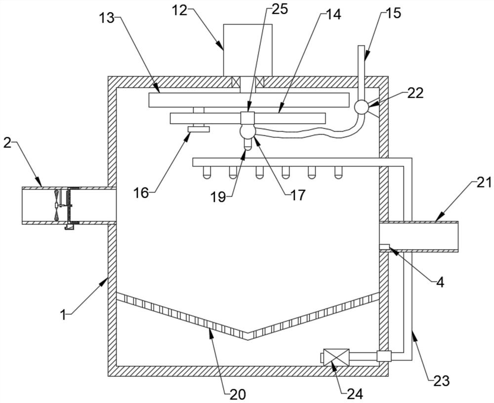
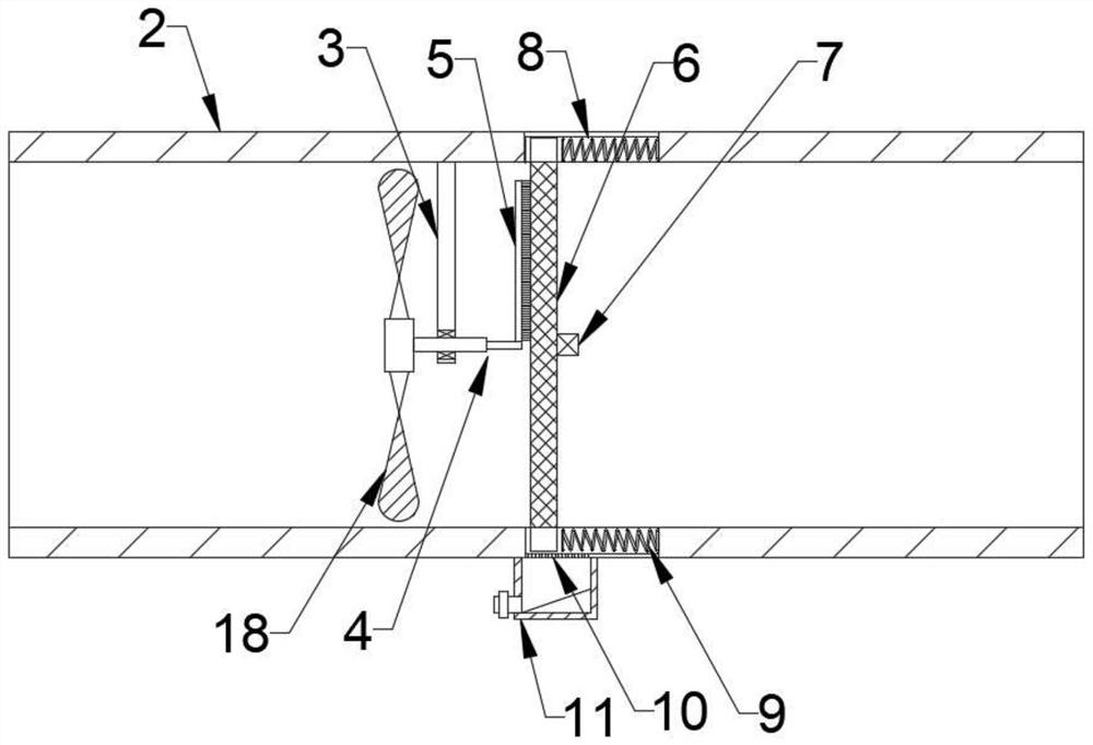
[0022] see Figure 1~5 , in an embodiment of the present invention, a straw incineration monitoring device includes a monitoring adsorption box 1 and a monitoring inlet pipe 2 and a monitoring outlet pipe 21 installed on both sides of the monitoring adsorption box 1, and a gas detection pipe 21 is installed in the monitoring outlet pipe 21 Instrument 27, a mounting frame 3 is fixed on the inner wall of the monitoring intake pipe 2, and a rotating rod 4 is installed on the mounting frame 3, and a paddle 18 and a brush seat 5 are respectively fixed on the rotating rod 4 from the inside to the outside to monitor the position of the intake pipe 2. The inner wall is provided with a chute 8, and the first filter screen 6 is slid on the chute 8. One side of the first filter screen 6 is connected with the groove wall of the chute 8 by a return spring 9, and the other side is connected with the brush holder 5 The bristles arranged on the upper part are kept in close contact, a vibratio...
Embodiment 2
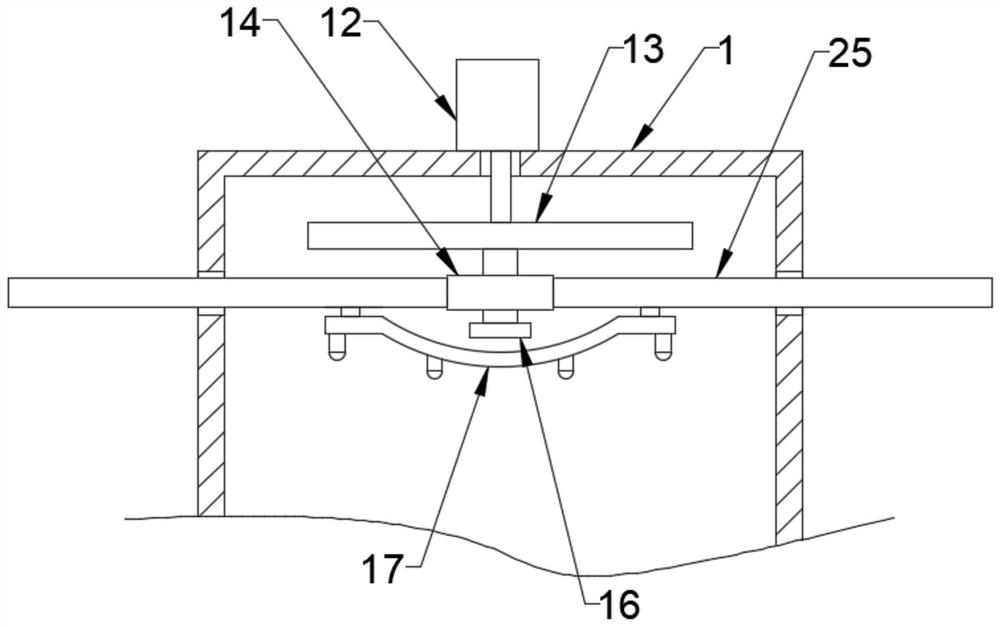
[0027] see Figure 1~5 As another preferred embodiment of the present invention, the adsorption assembly includes a water delivery pipe 15, a water collection pipe 17 and a mist nozzle 19, and the mist nozzle 19 is provided with a plurality of mist nozzles 19 evenly distributed on the bottom of the water collection pipe 17, The water collection pipe 17 is fixed on the bottom of the sliding rod 25, and the sliding rod 25 is slidingly clamped between the inner and outer walls of the monitoring adsorption box 1 and driven by a reciprocating mechanism. , Water delivery pump 22 is also installed on the delivery pipe 15.
[0028] Preferably, the reciprocating mechanism includes a turntable 13, a waist rod 14 and a pin 16, and a drive motor 12 is installed on the monitoring adsorption box 1. The turntable 13 is arranged horizontally and its top center is fixed to the shaft extension end of the drive motor 12, and the pin The column 16 is fixed on the eccentric bottom of the turntabl...
Embodiment 3
[0032] see Figure 1~5 , as another preferred embodiment of the present invention, a second filter screen 20 is installed on the inner bottom of the monitoring adsorption box 1, and a circulating water pipe 23 is also installed on the monitoring adsorption box 1, and the circulating water pipe 23 straddles the second filter screen Between the top and the bottom of 20, circulating water pump 24 is installed on circulating water pipe 23, and the top of circulating water pipe 23 is horizontally arranged, and several mist nozzles 19 are also installed on the horizontal pipe body of circulating water pipe 23.
[0033] Preferably, the circulating water pump 24 is arranged at the inner bottom of the monitoring adsorption box 1, and the connection between the circulating water pipe 23 and the monitoring adsorption box 1 is sealed.
[0034] In this embodiment, the settled sewage is filtered through the second filter screen 20 , and the circulating water pipe 23 and the circulating wate...
PUM
 Abstract
Description
Claims
Application Information
 - R&D Engineer
- R&D Manager
- IP Professional
- Industry Leading Data Capabilities
- Powerful AI technology
- Patent DNA Extraction
Browse by: Latest US Patents, China's latest patents, Technical Efficacy Thesaurus, Application Domain, Technology Topic, Popular Technical Reports.
© 2024 PatSnap. All rights reserved.Legal|Privacy policy|Modern Slavery Act Transparency Statement|Sitemap|About US| Contact US: help@patsnap.com