Lifting pot

A lifting device and synchronous lifting technology, which is applied in the field of lifting pots, can solve the problems of small application range, high cost, and inconvenient cleaning, and achieve the effects of simple and reasonable structural design, reduced volume and cost, and increased use range

Pending Publication Date: 2021-07-23
FOSHAN SHUNDE CHUANGUI APPLIANCE CO LTD
View PDF0 Cites 0 Cited by
  • Summary
  • Abstract
  • Description
  • Claims
  • Application Information

AI Technical Summary

Problems solved by technology

This kind of lifting pot is limited by the installation requirements of the motor 4 and the lifting mechanism 5. The pot body cannot be used in conjunction with an induction cooker, an electric ceramic stove, or a gas stove. The scope of application is small, and the overall structure is complex and costly. Limited volume and not easy to clean

Method used


Image

  • Lifting pot
  • Lifting pot
  • Lifting pot

Examples


Embodiment 1

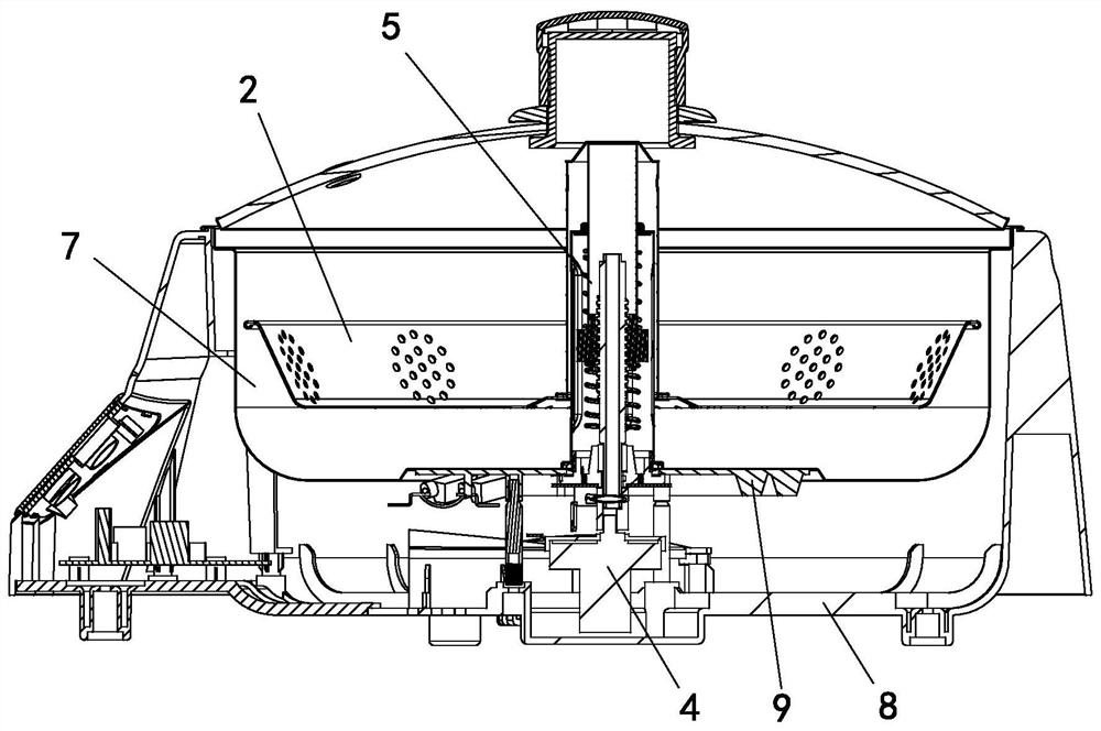
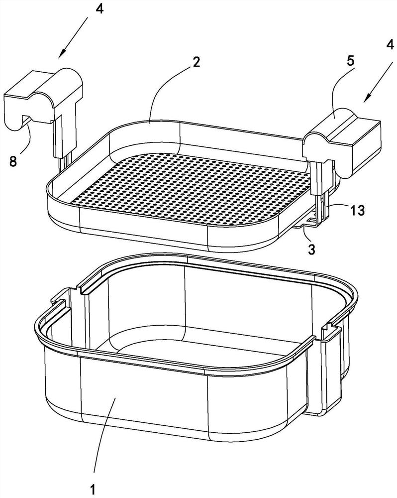
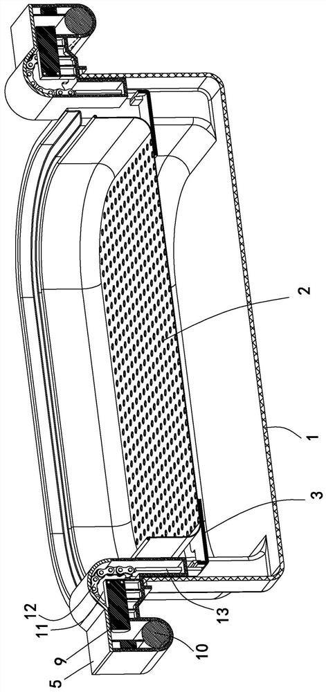
[0024] Embodiment 1, combining Figure 2 to Figure 4 , a lifting chafing dish, comprising a pot body 1 and a drain pan 2, the drain pan is arranged in the inner cavity of the pot body, and a hook bar 3 with holes is provided on the outside of the side wall of the drain pan 2, and the pot body 1 provides heating functions, such as electric heating, carbon Heated by fire or gas, the pot body heats the soup in the inner cavity and the food in the drain pan. The two ends of the drain pan 2 are respectively provided with a lifting device 4, and the lifting device 4 includes a housing 5 and a driving device arranged in the housing. 6 and lifter 7. The shell 5 is formed with a hooking part 8, which is hung on the top port of the pot body 1. Of course, the hooking part 8 can also be seated on the top port of the pot body 1, just extend the top port of the pot body 1 by a fold Side, hooking part 8 just can sit and be located at pot body top port, and housing 8 can support drain pan we...

Embodiment 2

[0027] Example 2, combined with Figure 5 , the difference between embodiment 2 and embodiment 1 is that the structure of the lifting member 7 is different, and the others are consistent. Suspender 13, screw rod 11 is threadedly connected with bevel gear 12, the other end of suspender 13 passes through housing 5, and the end of suspender 13 is provided with hook 14, and hook 14 is hooked in the hole of hook bar 3, and the motor 9 Drive shaft end is also provided with active bevel gear 15, and active bevel gear 15 drives bevel gear 12 to rotate, and bevel gear rotates and drives screw rod lifting, realizes boom synchronous lifting thereby realizes drain pan 2 lifting in pot body 1.

Embodiment 3

[0028] Example 3, combined with Figure 6 The difference between embodiment 3 and embodiment 1 is that the structure of the lifting member is different, and the others are the same. The lifting member 7 includes a rack 11 and a boom 13. One end of the rack 11 is connected to the boom 13, and the boom 13 The other end of 13 passes through the housing 5, the end of the suspension rod 13 is provided with a hook 14, and the hook 14 is hooked in the hole of the hook bar 3, the transmission shaft of the motor 9 is provided with a gear 15, and the gear 15 drives the rack 11 up and down, Realize the synchronous lifting of the suspension rod 13 so as to realize the lifting of the drain pan 2 in the pot body 1 .


PUM


Abstract

The invention relates to a lifting pot. The lifting pot comprises a draining plate, a pot body and a lifting device. The lifting device comprises a shell, a driving device and a lifting part, the driving device and the lifting part are arranged in the shell, the driving device drives the lifting part to ascend and descend, one end of the lifting part penetrates out of the shell to be connected with the draining plate, the shell can be erected on the pot body to support the weight of the draining plate, and the lifting part drives the draining plate to ascend and descend when ascending and descending. The lifting pot is simple and reasonable in structural design, the driving device and the lifting part are directly arranged in the shell to form a lifting device module, and the lifting device is directly arranged at the two ends of the draining plate, so that the size and cost of the lifting pot can be greatly reduced, and the use range of the draining plate is greatly enlarged. Only one pot body is provided, the draining plate is placed in the inner cavity of the pot body, the shell is erected at the top end opening of the pot body so that a hot pot can be lifted, the shell and the draining plate are convenient to disassemble and assemble, and the draining plate is more convenient to clean.

Description

technical field [0001] The invention relates to a lifting pot. Background technique [0002] Existing lifting hot pot, see figure 1 , the pot body includes an inner container 7 and a shell 8, a drain pan 2 is arranged in the inner container 7, a heating device 9 is provided at the bottom of the inner container 7, a motor 4 is arranged in the outer shell 8, and the bottom of the inner container 7 is driven by the motor 4 The lifting mechanism 5, the lifting end of the lifting mechanism 5 extends into the inner tank 7 to promote the drain pan 2 lifting. This kind of lifting pot is limited by the installation requirements of the motor 4 and the lifting mechanism 5. The pot body cannot be used in conjunction with an induction cooker, an electric ceramic stove, or a gas stove. The scope of application is small, and the overall structure is complex and costly. The volume is limited and it is not easy to clean. Contents of the invention [0003] Therefore, the object of the pr...

Claims


Application Information

Patent Timeline
IPC IPC(8): A47J27/10A47J36/00A47J36/20
CPCA47J27/10A47J36/00A47J36/20
Inventor 范启鑫
Owner FOSHAN SHUNDE CHUANGUI APPLIANCE CO LTD
Why Eureka
Try Eureka