
Variable-camber wing leading edge functional strength test load loading device

A technology for wing leading edge and strength testing, which is applied in the direction of applying stable bending force to test material strength, measuring device, strength characteristics, etc. The leading edge of the cambered wing is smooth, continuously deformed, and cannot be effectively coordinated.

Pending Publication Date: 2021-07-20
CHINA AIRPLANT STRENGTH RES INST
View PDF0 Cites 5 Cited by
  • Summary
  • Abstract
  • Description
  • Claims
  • Application Information

AI Technical Summary

Problems solved by technology

[0005] 1) Deformation and aerodynamic load loading cannot achieve smooth and continuous deformation of the leading edge of the variable camber wing;
[0006] 2) Deformation and aerodynamic load loading cannot be effectively coordinated, and the real-time deformation of the leading edge of the variable camber wing under the flight state of the aircraft cannot be simulated;
[0007] 3) Aerodynamic load loading cannot adapt to the large curvature and large deformation of the leading edge of the variable camber wing

Method used


Image

  • Variable-camber wing leading edge functional strength test load loading device

Examples


Embodiment Construction

[0038] In order to make the technical solution of the present application and its advantages clearer, the technical solution of the present application will be further clearly and completely described in detail below in conjunction with the accompanying drawings. It can be understood that the specific embodiments described here are only part of the application Examples are only used to explain the present application, not to limit the present application. It should be noted that, for the convenience of description, only the parts related to the present application are shown in the drawings, and other relevant parts can refer to the general design. In the case of no conflict, the embodiments in the application and the technologies in the embodiments Features can be combined with each other to obtain new embodiments.

[0039] In addition, unless otherwise defined, the technical terms or scientific terms used in the description of the application shall have the usual meanings und...


PUM


Abstract

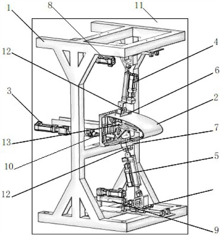
The invention belongs to the technical field of variable-camber wing leading edge functional strength tests, and particularly relates to a variable-camber wing leading edge functional strength test load loading device which comprises: a supporting frame used for being connected to a variable-camber wing leading edge; a deformation driving motor which is connected to the supporting frame and used for being connected to a driving connecting rod mechanism at the root of the front edge of the variable-camber wing so as to apply a deformation load to the front edge of the variable-camber wing; an upper airfoil aerodynamic load loading actuator cylinder, wherein the cylinder body of theupper airfoil aerodynamic load loading actuator cylinder is connected to the supporting frame in a sliding mode, and a piston rod of the upper airfoil aerodynamic load loading actuator cylinder is used for being connected to the upper airfoil of the front edge of the variable-camber wing so that aerodynamic loads can be applied in the normal direction of the upper airfoil of the front edge of the variable-camber wing; a lower airfoil aerodynamic load loading actuator cylinder, wherein a cylinder body of the lower airfoil aerodynamic load loading actuator cylinder is connected to the lower portion of the supporting frame in a sliding mode, and a piston rod of the lower airfoil aerodynamic load loading actuator cylinder is used for being connected to the lower airfoil of the front edge of the variable-camber wing so that aerodynamic loads can be applied in the normal direction of the lower airfoil of the front edge of the variable-camber wing.

Description

technical field [0001] The application belongs to the technical field of the functional strength test of the leading edge of the variable camber wing, and in particular relates to a load loading device for the functional strength test of the leading edge of the variable camber wing. Background technique [0002] The variable camber wing surface is continuous and smooth without slots or sliding joints, and its leading and trailing edges are flexible structures, which have many advantages such as high lift-to-drag ratio, low drag, low noise, and good stealth. [0003] The leading edge of the variable camber wing is the key part of its function realization. It is of great significance for the improvement and optimization of the variable camber wing to perform tests on the functional strength of the variable camber wing leading edge to obtain relevant data. [0004] Based on the current test device for the functional strength test of the leading edge of the variable camber wing,...

Claims


Application Information

Patent Timeline
IPC IPC(8): G01N3/20
CPCG01N3/20G01N2203/0003G01N2203/0023G01N2203/0044G01N2203/0682Y02T90/00
Inventor 李珊山陈先民沈子实李三元
Owner CHINA AIRPLANT STRENGTH RES INST
Learn More