
Hydrogen combustion chamber based on axial vortex opposite arrangement mixing

A combustion chamber, axial technology, applied in the combustion chamber, continuous combustion chamber, combustion method, etc., can solve the complex structure of the transverse jet micro-mixing combustion chamber, the difficulty of burning high-concentration hydrogen and pure hydrogen, and the high design and test costs. problems, to achieve the effect of improving the combustion power per unit volume, fast processing speed, and cheap geometric modeling

Active Publication Date: 2021-07-20
INST OF ENGINEERING THERMOPHYSICS - CHINESE ACAD OF SCI
View PDF7 Cites 3 Cited by
  • Summary
  • Abstract
  • Description
  • Claims
  • Application Information

AI Technical Summary

Problems solved by technology

The low-pollution combustion chamber modified based on this combustion technology can only burn part of the hydrogen, and it is difficult to burn high-concentration hydrogen and pure hydrogen
At the same time, the modified dry-low combustion chamber has a more complex structure, high design and test costs, and a large number of modifications to the combustion chamber will cause changes in the overall layout of the machine and increase research and development costs.
In addition, the existing pure hydrogen combustor adopts lean oil direct injection technology, which has high combustion temperature and high pollutant emissions; the structure of the transverse jet micro-mixing combustor is complicated, and the processing cost is high

Method used


Image

  • Hydrogen combustion chamber based on axial vortex opposite arrangement mixing
  • Hydrogen combustion chamber based on axial vortex opposite arrangement mixing
  • Hydrogen combustion chamber based on axial vortex opposite arrangement mixing

Examples


Embodiment Construction

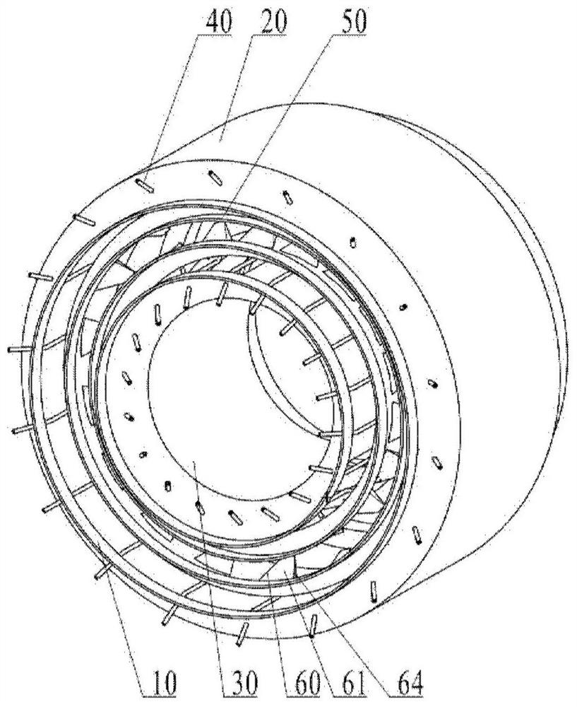
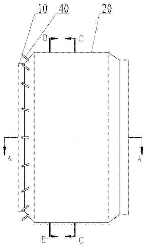
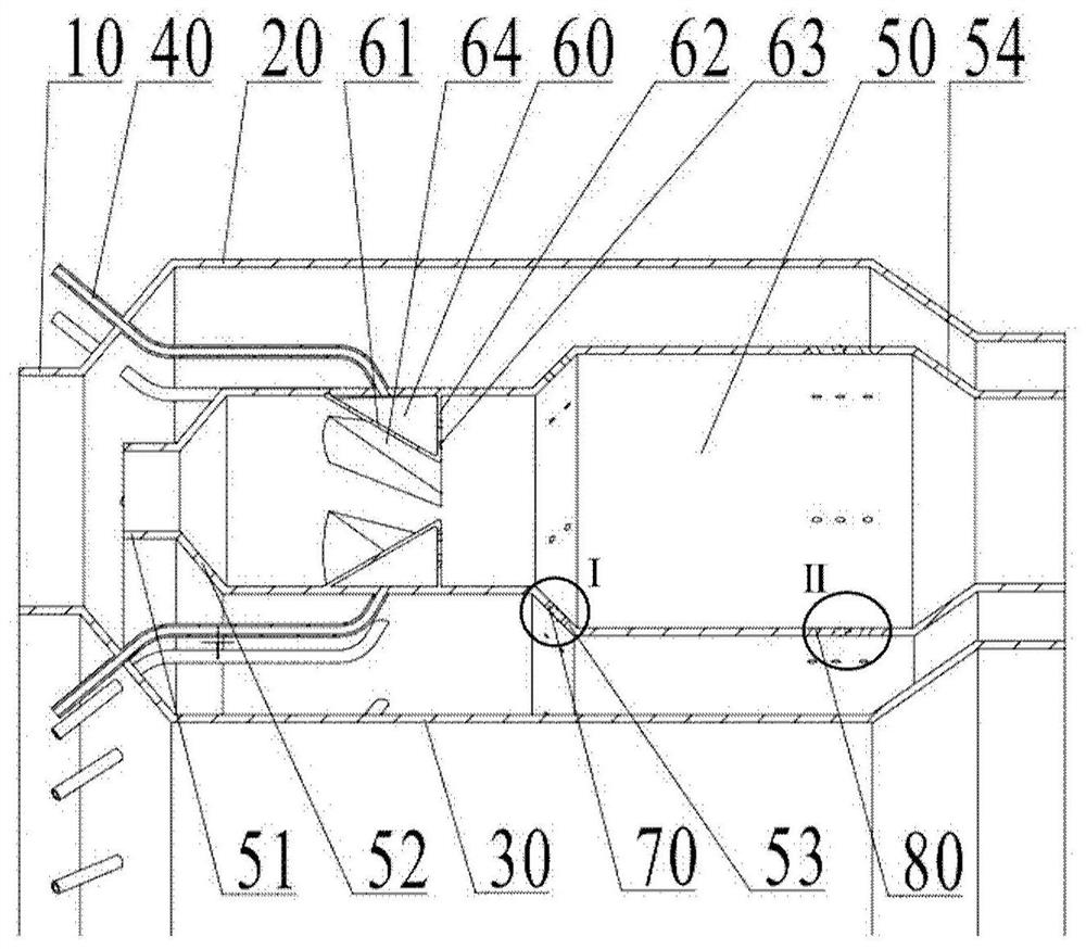
[0059] The present disclosure provides a hybrid hydrogen combustor based on an axial vortex pair arrangement, including a flame cylinder, an outer casing, an inner casing, and at least two axial vortex generators. The flame tube includes an outer ring and an inner ring; the outer casing and the outer ring of the flame tube form an air circulation channel; the inner casing is fixedly connected to the inside of the outer casing, and the inner casing and the inner ring of the flame tube form an air circulation channel. aisle. The axial vortex generator is a tetrahedral cavity, and the axial vortex generators are fixedly connected to the outer ring and the inner ring of the flame tube respectively, which is suitable for generating axial vortex so that hydrogen fuel can be effectively mixed and burned without blowing out , Tempering and other issues. The hydrogen combustor based on the axial vortex arrangement in this disclosure for blending proposes a design scheme combining the ...


PUM


Abstract

The invention provides a hydrogen combustion chamber based on axial vortex opposite arrangement mixing. The hydrogen combustion chamber comprises a flame tube which comprises an outer ring and an inner ring, an outer casing, an inner casing and at least two axial vortex generators; an air circulation outer channel is defined by the outer casing and the outer ring of the flame tube; the inner casing is fixedly connected inside the outer casing, and an air circulation inner channel is defined by the inner casing and the inner ring of the flame tube; each axial vortex generator is a tetrahedral cavity; the axial vortex generators are fixedly connected to the outer ring and the inner ring of the flame tube respectively and are suitable for providing axial vortexes to enable fuel to be mixed and combusted. According to the hydrogen combustion chamber based on axial vortex opposite arrangement mixing, the design scheme that the axial vortexes and tiny tangential jet flow are combined is provided, the axial vortexes are generated by the tetrahedral structures for mixing, compared with a combustion chamber adopting a swirler, the hydrogen combustion chamber has the advantages that no backflow area and no low-speed area exist, pure hydrogen can be effectively combusted, and the problems of tempering, self-ignition and unstable combustion are solved.

Description

technical field [0001] The present disclosure relates to the field of gas turbines, in particular to a hydrogen combustor based on an axial vortex pair arrangement. Background technique [0002] As the international and domestic requirements for low-carbon and clean energy are gradually increasing, the pressure on carbon emissions is increasing. As hydrogen is a representative of low-carbon and clean energy in the future, it is of strategic significance to study the thermal conversion and utilization of hydrogen energy. Hydrogen is a low-carbon and clean energy. Combusting hydrogen with a gas turbine is a typical method of hydrogen energy utilization. Compared with natural gas fuel, the flame propagation speed of hydrogen is extremely fast and the flame surface is more prone to wrinkling, thermoacoustic oscillation and tempering. As a result, it is difficult to burn pure hydrogen or high-concentration hydrogen in the existing low-pollution gas turbine combustor based on lean...

Claims


Application Information

Patent Timeline
Patent Type & Authority Applications(China)
IPC IPC(8): F23R3/28F23R3/36F23R3/42F23R3/58
CPCF23R3/36F23R3/58F23R3/286F23R3/42Y02E20/34
Inventor 杨旸余志健
Owner INST OF ENGINEERING THERMOPHYSICS - CHINESE ACAD OF SCI
Learn More