
Cluster type energy storage system

An energy storage system and cluster technology, applied in the field of energy storage, can solve the problems of lower assembly efficiency, complex adaptation work, inconvenient promotion and implementation, etc., and achieve the effects of reducing costs, improving assembly and debugging efficiency, and good practical value

Pending Publication Date: 2021-07-16
上海采日能源科技有限公司
View PDF0 Cites 0 Cited by
  • Summary
  • Abstract
  • Description
  • Claims
  • Application Information

AI Technical Summary

Problems solved by technology

Existing large-scale energy storage systems mainly include: centralized energy storage systems and string energy storage systems; among them, the centralized energy storage system mainly consists of multiple single cells connected in series and parallel to form a system, any single cell The failure of the battery cells will affect the operation of the entire energy storage system; the string energy storage system is formed by connecting multiple single-cluster energy storage systems in parallel, each single-cluster energy storage system includes multiple battery packs, in order to ensure that each For the individual charge and discharge management of battery packs, each battery pack is equipped with a corresponding optimizer, and each single-cluster energy storage system is equipped with a controller. Therefore, in the actual assembly process of the energy storage system, complex adaptation The work reduces the assembly efficiency, and increases the cost of the energy storage system, which is not easy to promote and implement in practical applications

Method used


Image

  • Cluster type energy storage system
  • Cluster type energy storage system
  • Cluster type energy storage system

Examples


Embodiment Construction

[0023] In order to make the purpose, technical solutions and advantages of the embodiments of the present invention clearer, the technical solutions of the present invention will be clearly and completely described below in conjunction with the accompanying drawings. Obviously, the described embodiments are part of the embodiments of the present invention, not all of them. the embodiment. Based on the embodiments of the present invention, all other embodiments obtained by persons of ordinary skill in the art without making creative efforts belong to the protection scope of the present invention.

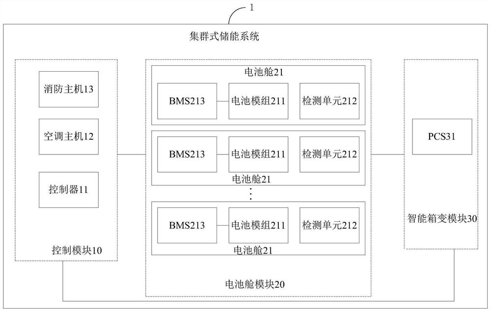
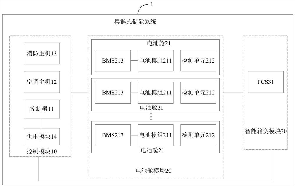
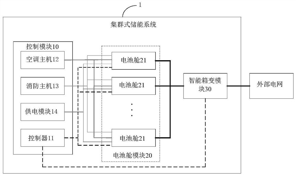
[0024] Aiming at the problem of high cost of the existing large-scale energy storage system, the embodiment of the present invention provides a cluster energy storage system, which realizes multiple Shared charging and discharging management, shared air-conditioning management, and shared fire management for each battery compartment reduce the cost of the energy storage system, impro...


PUM


Abstract

The invention provides a cluster type energy storage system. The cluster type energy storage system comprises a control module, a battery cabin module and an intelligent box transformer substation module, wherein the intelligent box transformer substation module comprises a PCS; the control module comprises a controller, an air conditioner host and a fire-fighting host; the battery cabin module comprises a plurality of battery cabins connected in parallel; each battery cabin further comprises a battery module, a detection unit and a BMS connected with the battery module and the controller; the controller is used for generating a first control instruction according to battery parameters of the battery module acquired by the BMS, and sending the first control instruction to a PCS so as to enable the PCS to perform charging and discharging management on the battery module according to the first control instruction; and the air conditioner host and the fire-fighting host are used for managing the environment in the battery cabins according to the detection information, collected by a detection unit, of the battery cabins. According to the cluster type energy storage system, the cost of the energy storage system is reduced, the charge and discharge management, temperature control effect and fire protection effect of the energy storage system are ensured, and the cluster type energy storage system has good practical value.

Description

technical field [0001] The invention relates to the technical field of energy storage, in particular to a clustered energy storage system. Background technique [0002] Large-scale energy storage systems will play an indispensable role in the future power system due to the needs of large-scale access to the power grid of new energy, power peak shaving and valley filling, participation in voltage regulation and frequency regulation, and development of micro-grids. Existing large-scale energy storage systems mainly include: centralized energy storage systems and string energy storage systems; among them, the centralized energy storage system mainly consists of multiple single cells connected in series and parallel to form a system, any single cell The failure of the battery cells will affect the operation of the entire energy storage system; the string energy storage system is formed by connecting multiple single-cluster energy storage systems in parallel, each single-cluster ...

Claims


Application Information

Patent Timeline
Patent Type & Authority Applications(China)
IPC IPC(8): H02J3/32
CPCH02J3/32
Inventor 徐鹏飞李峰王健鹏赵佳航
Owner 上海采日能源科技有限公司
Learn More