
Short material edge sealing and feeding device for edge sealing process in furniture industry

A feeding device and an industry-leading technology, applied in the field of short-material edge-banding feeding devices, can solve problems such as difficulty in ensuring the safety of operators, pressure on the operator's pressure beam, and difficulty in ensuring verticality, etc., to improve operational safety and clamping performance Effect of stabilizing and expanding the processing range

Pending Publication Date: 2021-07-16
泰州市龙洋木业有限公司
View PDF0 Cites 0 Cited by
  • Summary
  • Abstract
  • Description
  • Claims
  • Application Information

AI Technical Summary

Problems solved by technology

But in reality, due to the existence of the pressure beam, if the material is fed manually and a posture perpendicular to the chain conveying direction is required, it is very difficult to ensure the safety of the operator and the quality of the processing, and there is a certain danger to the processing of shorter workpieces. Even if it can be fed and processed, it is difficult to guarantee the perpendicularity to the conveying direction, and the processing quality is not high
[0003] In the unilateral edge banding process applied to the panel home processing process, the unilateral edge banding equipment has certain requirements for the minimum length of the workpiece, basically for the workpiece that meets the minimum requirements, because when feeding, the edge banding surface needs to be It is attached to the feed backer and pushed to the bottom of the pressure beam of the edge banding machine. The actual operation speed is relatively slow, and there is a certain danger. The operator's hand may be pressed by the pressure beam.

Method used


Image

  • Short material edge sealing and feeding device for edge sealing process in furniture industry
  • Short material edge sealing and feeding device for edge sealing process in furniture industry
  • Short material edge sealing and feeding device for edge sealing process in furniture industry

Examples


Embodiment Construction

[0021] The following will clearly and completely describe the technical solutions in the embodiments of the present invention with reference to the accompanying drawings in the embodiments of the present invention. Obviously, the described embodiments are only some, not all, embodiments of the present invention. Based on the embodiments of the present invention, all other embodiments obtained by persons of ordinary skill in the art without making creative efforts belong to the protection scope of the present invention.

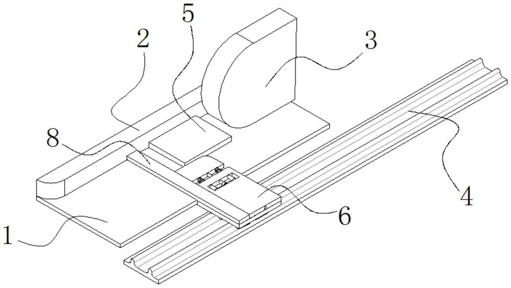
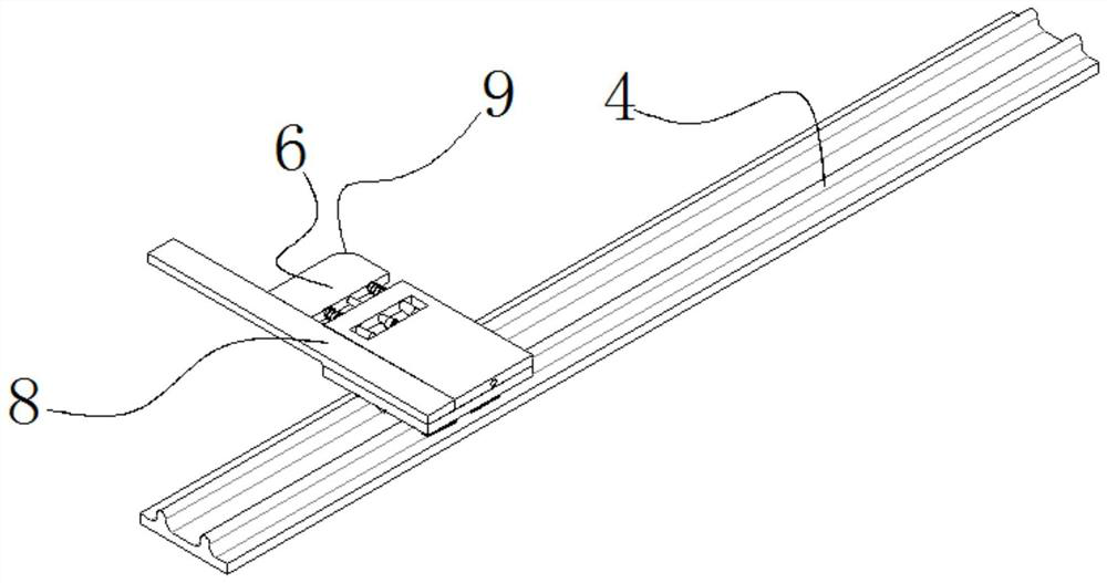
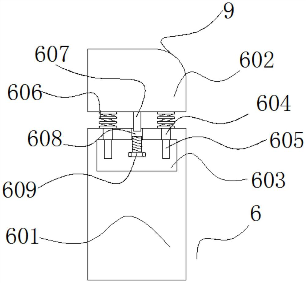
[0022] see Figure 1-4 , the present invention provides a technical solution: a short-material edge-banding feeding device for the edge-banding process in the furniture industry, including a feed table 1 and a semicircle guide rail base 4, the semicircle guide rail base 4 is a double guide rail slider base, so that The feeding mechanism 6 moves more smoothly on the semicircle guide rail base 4. The double guide rail slider base is composed of the traditional s...


PUM


Abstract

The invention discloses a short material edge sealing and feeding device for the edge sealing process in the furniture industry. The short material edge sealing and feeding device comprises a feeding table and a semicircular guide rail base, and a feeding backer is welded to the upper surface of the feeding table. According to the short material edge sealing and feeding device, a fixing plate is pushed to push a workpiece to the position below a pressing beam of an edge sealing machine, an operator only needs to place the workpiece at the proper position of the feeding table with one hand and pushes the fixing plate with the other hand, the fixing plate is located on the outer side of the pressing beam of the edge sealing machine, the risk that the hands are pressed is completely avoided, the edge sealing machine machines the workpiece, the operation safety of the equipment is greatly improved, operation is easy, the production efficiency is high, the clamping performance is stable, and the product quality is high; and the elastic range is adjusted by a screw, the depth of the screw in a threaded hole is controlled, so that a feeding mechanism can clamp workpieces in different ranges, the machinable range of the equipment is expanded, and the device is modularly designed and can be mounted on all single-side edge sealing machines.

Description

technical field [0001] The invention belongs to the technical field of feeding equipment, and in particular relates to a short-material edge-sealing feeding device for an edge-sealing process in the furniture industry. Background technique [0002] The edge banding process is an important process in the panel furniture industry and is widely used in the home production industry. The edge banding process is generally completed by an edge banding machine, and the edge banding machine generally requires a certain amount of overhang during processing, normally around 30mm, and the conveyor chain itself has a certain width, normally around 100mm. Theoretically, the edge banding machine can perform edge banding on workpieces whose length exceeds 130mm. But in reality, due to the existence of the pressure beam, if the material is fed manually and a posture perpendicular to the chain conveying direction is required, it is very difficult to ensure the safety of the operator and the ...

Claims


Application Information

Patent Timeline
Patent Type & Authority Applications(China)
IPC IPC(8): B65G47/74B27N7/00
CPCB27N7/00B65G47/74B65G2201/0282
Inventor 王家国黄雄杰闫荣兴
Owner 泰州市龙洋木业有限公司
Learn More