Goods lifting equipment for construction machinery
A technology for construction machinery and cargo, which is applied to portable lifting devices, hoisting devices, etc. It can solve the problems of cumbersome installation process and inaccurate and stable lifting effect, and achieve the effects of improving installation efficiency, installation stability, and easy positioning
- Summary
- Abstract
- Description
- Claims
- Application Information
AI Technical Summary
Problems solved by technology
Method used
Image

Examples
Embodiment 1
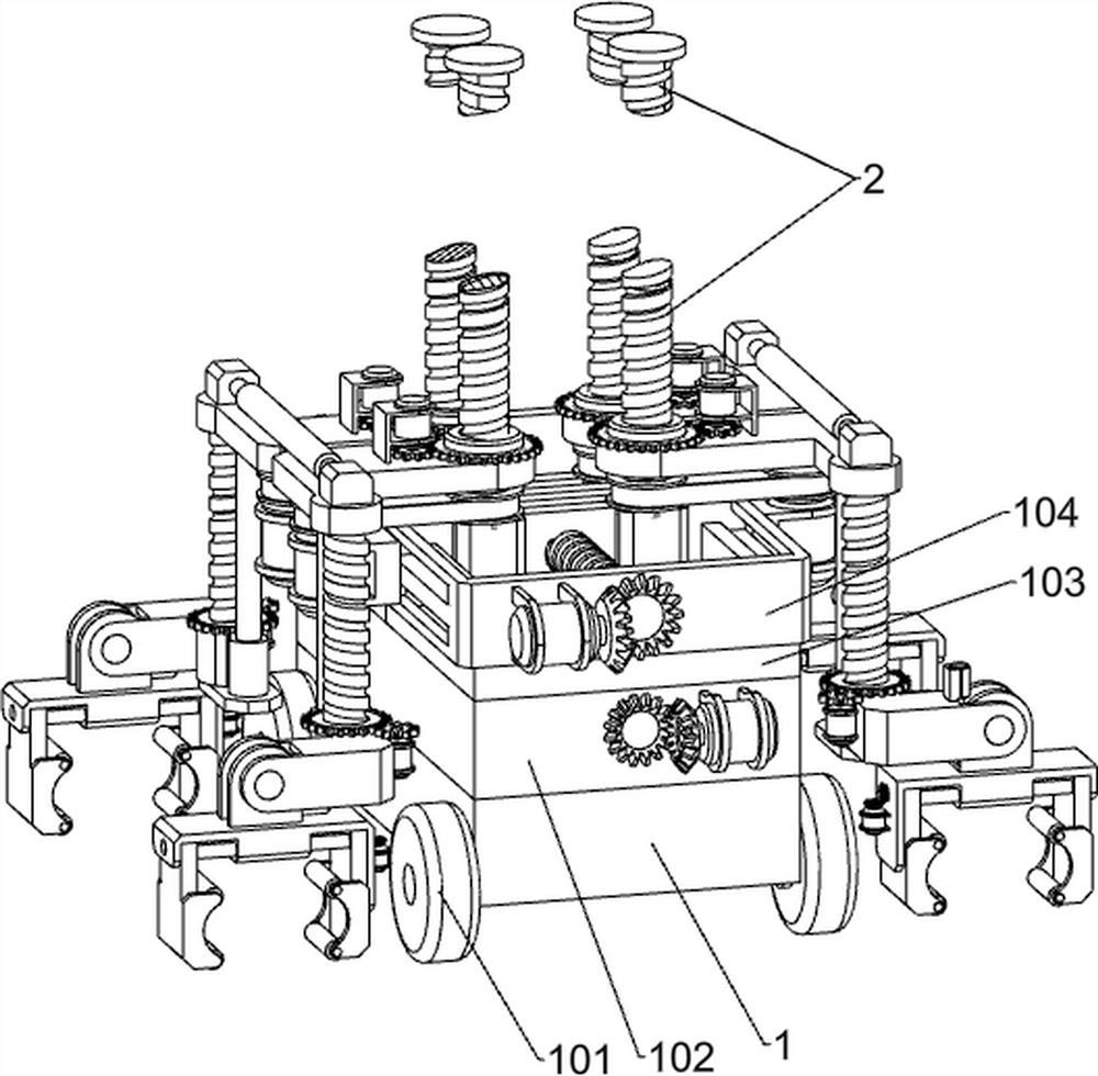
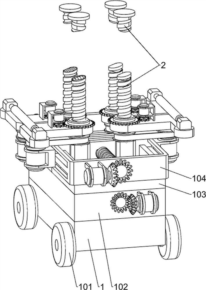
[0040] A construction machinery cargo lifting device, such as figure 1 , figure 2 and Figure 8 Shown, comprise moving mechanism, wheel 101, turret 102, sliding plate 103, car body fixing frame 104, first sliding frame 105, first elevating mechanism and grasping mechanism, wheel 101 is provided with four, vehicle frame 1 Four wheels 101 are rotatably connected to both sides of the turret 102, the turret 102 is arranged on the upper side of the vehicle frame 1, four slotted holes are opened under the turret 102, two sliding plates 103 are provided, and the two sliding plates 103 are arranged on the rotating Above the frame 102, two car body fixing frames 104 are provided with two, and the two car body fixing frames 104 are respectively fixedly connected above the two sliding plates 103, and the first sliding frame 105 is slidably connected in the slideway inside the car body fixing frame 104, There are four first lifting mechanisms, the four first lifting mechanisms are resp...
Embodiment 2
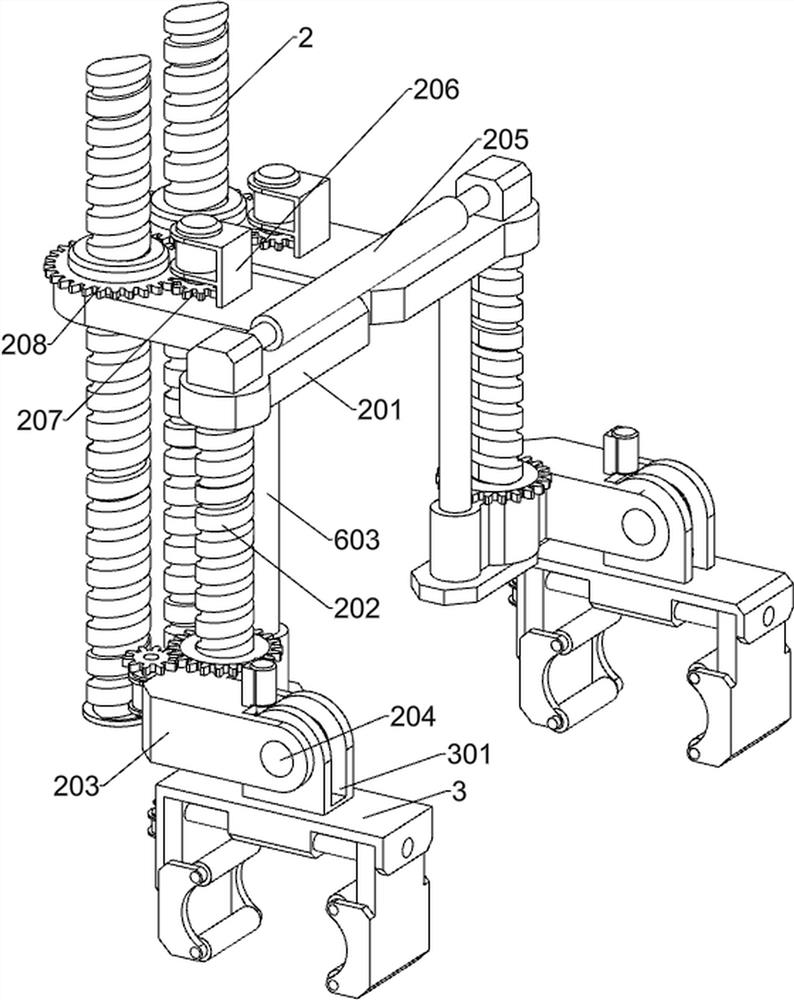
[0042] On the basis of Example 1, such as image 3 As shown, the first lifting mechanism includes a first threaded rod 2, a lifting frame 201, a second threaded rod 202, a turning frame 203, a rotating shaft 204, a telescopic guide rod 205, an eighth motor 206, a second spur gear 207 and a first A gear threaded sleeve 208, four first threaded rods 2 are provided, the four first threaded rods 2 are respectively slidably connected to the two first sliding frames 105, four lifting frames 201 are provided, and the lifting frame 201 is L-shaped, The four lifting frames 201 are respectively slidably connected to the four first threaded rods 2. There are four first gear threaded sleeves 208, and the four first gear threaded sleeves 208 are respectively connected to the four lifting frames 201 in rotation. The eighth motor 206 There are four, the four eighth motors 206 are fixedly connected to the four lifting frames 201 respectively, the second spur gears 207 are provided with four, ...
Embodiment 3
[0045] On the basis of Example 2, such as Figure 4-7 As shown, the grabbing mechanism includes a grabbing frame 3, a hinge 301, a clamping frame 302, a first motor 303, a first bevel gear 304, a first two-way threaded rod 305, a second bevel gear 306 and a sliding rod 307, and grabbing There are four grabbing mechanisms, the four grabbing mechanisms are respectively connected to the four rotating shafts 204, the upper side of the grabbing frame 3 is fixedly connected with a hinge 301, the hinge 301 is fixedly connected to the rotating shaft 204, the clamping frame 302 and the sliding rod 307 are respectively provided with two, and the two ends of two sliding rods 307 are respectively fixedly connected to the inner two ends of grabbing frame 3, and two clamping frames 302 are arranged symmetrically on the inner side of grabbing frame 3 respectively, and two clamping frames 302 slide Connected to two sliding rods 307, the first two-way threaded rod 305 penetrates the grab frame...
PUM
 Abstract
Description
Claims
Application Information
 - R&D
- Intellectual Property
- Life Sciences
- Materials
- Tech Scout
- Unparalleled Data Quality
- Higher Quality Content
- 60% Fewer Hallucinations
Browse by: Latest US Patents, China's latest patents, Technical Efficacy Thesaurus, Application Domain, Technology Topic, Popular Technical Reports.
© 2025 PatSnap. All rights reserved.Legal|Privacy policy|Modern Slavery Act Transparency Statement|Sitemap|About US| Contact US: help@patsnap.com