
Integrated ball valve element plug valve and assembling method

A technology for plug valves and ball valves, applied in the field of integrated ball valve core plug valves and assembly, which can solve the problems of scattered parts, complex structure, unfavorable site management, etc.

Pending Publication Date: 2021-07-06
成都海猛石油机械有限公司
View PDF3 Cites 0 Cited by
  • Summary
  • Abstract
  • Description
  • Claims
  • Application Information

AI Technical Summary

Problems solved by technology

[0003] With the increasingly higher requirements for oilfield production safety, cost reduction, and speed-up and efficiency improvement, and at the same time, the production batch is getting larger and larger. Before leaving the factory, every set of products, regardless of whether they are old or new, must be sealed under pressure before they are used in wells. The test and detection have brought great pressure to the production and maintenance sites, especially when there is a need for large-scale and fast operations. Due to the complex structure and many parts of the existing plug valves, it is difficult for the disassembly and maintenance site equipment, tooling conditions and personnel skills. The level requirements are high, and the accessories provided by the manufacturer are relatively scattered, which is not conducive to on-site management. This puts forward an urgent requirement for integration and modularization of the ball valve core of the plug valve, requiring the maintenance of accessories to be simple, convenient and fast. Moreover, the qualification rate of suppression must be guaranteed to achieve the purpose of saving assembly and disassembly maintenance time, reducing costs and increasing efficiency

Method used


Image

  • Integrated ball valve element plug valve and assembling method
  • Integrated ball valve element plug valve and assembling method
  • Integrated ball valve element plug valve and assembling method

Examples


no. 1 example

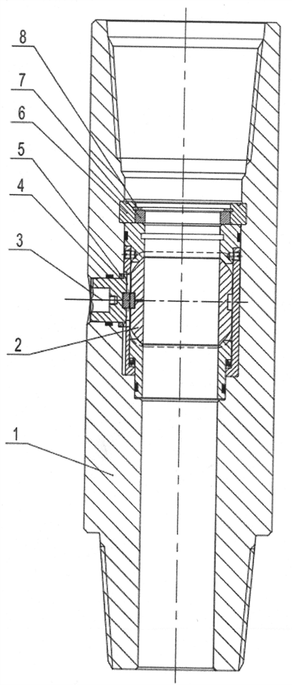
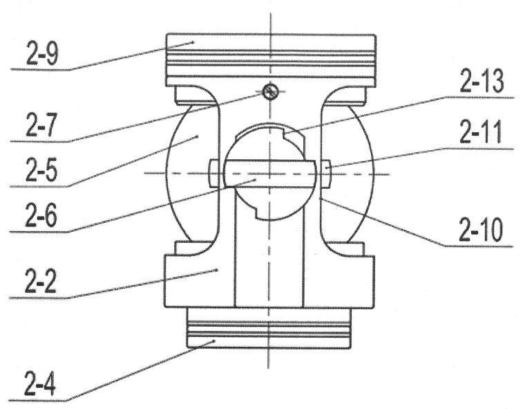
[0033] Please refer to figure 1 This embodiment provides an integrated balloon plug valve and assembly method comprising a 1-valve body, a 3-operation key, 3-operation key, and 1-valve body fitting, 1-valve body 5-sealed gasket set between steps, 1-integrated ball valve, 6-set, 7-support sleeve, and 8-hole, 2-integrated ball valve core; 2-integrated ball valve core - Mounting tube, 2-3-wave spring, 2-4-, 2-5-ball, 2-6-convex bond and 2-9-upper club composition; 2-2-mounting tube down part The surface of the stepped holes and 2-4-lower outer circumstances are formed with 2-3-wave spring, 2-2-mounting tubes, 2-6-convex keys and 2-5- The core, the upper inner hole of the 2-2-mounting tube is set on the lower outer step of 2-9- upper club, and the screw is fixedly connected by the 2-7-cylindrical end slot; 1-valve body inner wall Setting 4-Seal 1 between the 3-Operation Key; 1-Valve body and 2-4-, 2-1-sealing rings 2 and 2-8, respectively, and 2-9-upper spherical seats. - Sealing ring...


PUM


Abstract

The invention discloses an integrated ball valve element plug valve and an assembling method. The integrated ball valve element plug valve comprises a valve body, an operation key, an integrated ball valve element, a splicing ring, a supporting sleeve and an elastic check ring for a hole, wherein the integrated ball valve element is composed of a mounting cylinder, a wave spring, a lower ball seat, a ball element, a convex key, sealing rings and an upper ball seat, the wave spring is sleeved in an annular space formed by a lower step hole of the mounting cylinder and a lower outer circle step of the lower ball seat, the convex key and the ball element are arranged in the middle of the mounting cylinder, an upper inner hole of the mounting cylinder is sleeved on a lower outer circle step of the upper ball seat and is fixedly connected with the lower outer circle step through a set screw, so that integration and modularization of the ball valve element are realized, the sealing rings are respectively arranged in a hole, matched with the operating key, of the valve body and on the upper and lower ball seats, the operation key and the ball element are connected in a matched mode through the convex key and rotate, and opening / closing of the plug valve is achieved. The integrated ball valve element is novel in structure, simple, reliable, low in machining difficulty and particularly convenient to disassemble and assemble, assembly, maintenance, disassembly and replacement of accessories on a production site are facilitated, and on-site management and cost saving are facilitated.

Description

Technical field [0001] The present invention relates to the field of drilling and construction, and in particular, there is an integrated balloon plug valve and assembly method. Background technique [0002] Currently, the plug valve is used as a drill anti-ball valve that has been widely used in drilling and repair construction operations at home and abroad, and is used to partition or connect fluid in the water eye. Open the valve drilling fluid during normal drilling into the drill strip, the closure valve can avoid drilling fluids on the well, which avoids the waste of drilling fluids and satisfies environmental requirements. [0003] With the requirements of oilfield production safety, cost reduction and speeding efficiency, the production batch is getting bigger and larger, each set of new products is factory factory, no matter the new and old, it must be sealed before use. Test detection, a great pressure on the production and maintenance site, especially when there is a l...

Claims


Application Information

Patent Timeline
Patent Type & Authority Applications(China)
IPC IPC(8): E21B21/10
CPCE21B21/10
Inventor 黄瑞海
Owner 成都海猛石油机械有限公司
Learn More