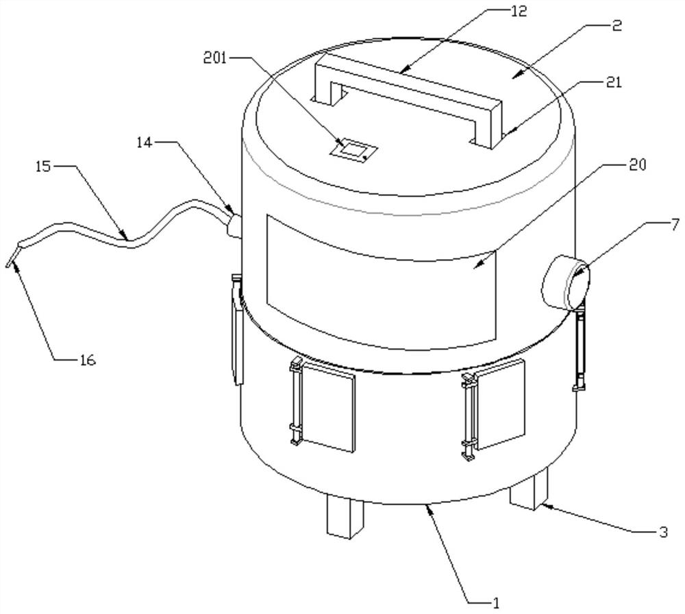
Liver ascites aspirator
An aspirator and a technique for hepatic ascites, which are applied to suction devices and other directions, can solve the problems of increasing the work intensity of medical staff, poor suction efficiency, and low suction volume, etc., and achieve the effects of reasonable structure design, convenient operation, and quality assurance.
- Summary
- Abstract
- Description
- Claims
- Application Information
AI Technical Summary
Problems solved by technology
Method used
Image
Examples
Embodiment 1
[0029] see Figure 1-7 As shown, this embodiment is a hepatic ascites suction device, including a lower casing 1 and an upper casing 2, a base 3 is connected around the bottom of the lower casing 1, and a first base is connected to the center of the bottom of the lower casing 1. Motor 4, the top power output end of the first motor 4 is connected with a support shaft 5, and one end of the support shaft 5 extending into the inner cavity of the lower casing 1 is connected with a collection assembly 6, and the right side wall of the upper casing 2 is connected with a second The motor 7 and the power output end of the second motor 7 are connected with a worm 8, the left side wall of the inner chamber of the upper housing 2 is connected with a fixed ring 9, the inner wall of the fixed ring 9 is connected with a piston cylinder 10, and the piston cylinder 10 is sealed and slidably connected There is a piston plate 11, a U-shaped rod 12 is connected to the top of the piston plate 11, ...
Embodiment 2
[0035] On the basis of Embodiment 1, the transmission mechanism 13 includes a first rotating shaft 131, a second rotating shaft 132 and a reciprocating frame 133. The first rotating shaft 131 is located below the second rotating shaft 132. The outer wall of the first rotating shaft 131 is connected with a worm wheel 134 and a belt. Wheel one 135, worm gear 134 is meshed and connected to worm screw 8, the outer wall of the second rotating shaft 132 is connected with half gear 136 and pulley two 137, and a transmission belt 138 is sleeved between pulley two 137 and pulley one 135, and the top of reciprocating frame 133 The U-shaped rod 12 is fixedly connected, and the inner wall of the reciprocating frame 133 is symmetrically connected with a rack 139 , and the teeth of the half gear 136 are engaged with the rack 139 .
[0036]A viewing window 20 is installed on the front end of the upper case 2 , and two guide holes 21 are provided on the top of the upper case 2 , and the vertic...
Embodiment 3
[0041] On the basis of the second embodiment, the aggregate assembly 6 includes a disc 601 fixedly connected to the top of the support shaft 5, an electric push rod 602 is connected to the top of the disc 601, and a lifting block 603 is connected to the movable end of the top of the electric push rod 602. The outer wall of the circumference of the disc 601 is evenly distributed with several groups of guide rods 604 in the circumferential direction, and the outer wall of the guide rod 604 is movably covered with a moving block 605, and a movable rod 606 is hinged between the top of the moving block 605 and the outer wall of the lifting block 603. A bracket 607 is connected to the outside of the top, and a liquid storage bottle 608 is installed in the bracket 607 , and a buffer spring 609 is connected between the moving block 605 and the disc 601 .
[0042] The side wall of the lower casing 1 is provided with several sets of outlets 101 in the circumferential direction, and the o...
PUM
 Abstract
Description
Claims
Application Information
 - R&D
- Intellectual Property
- Life Sciences
- Materials
- Tech Scout
- Unparalleled Data Quality
- Higher Quality Content
- 60% Fewer Hallucinations
Browse by: Latest US Patents, China's latest patents, Technical Efficacy Thesaurus, Application Domain, Technology Topic, Popular Technical Reports.
© 2025 PatSnap. All rights reserved.Legal|Privacy policy|Modern Slavery Act Transparency Statement|Sitemap|About US| Contact US: help@patsnap.com


