Camera module and electronic equipment

A technology of camera module and electronic equipment, which is applied in TV, electrical components, image communication, etc. It can solve the problems of inability to accurately calculate the focus point, inconsistency between the optical axis and the camera, and affect the user experience, so as to meet the needs of focusing and improve Accuracy, the effect of improving the degree of coincidence

Pending Publication Date: 2021-06-29
VIVO MOBILE COMM CO LTD
View PDF8 Cites 4 Cited by
  • Summary
  • Abstract
  • Description
  • Claims
  • Application Information

AI Technical Summary

Problems solved by technology

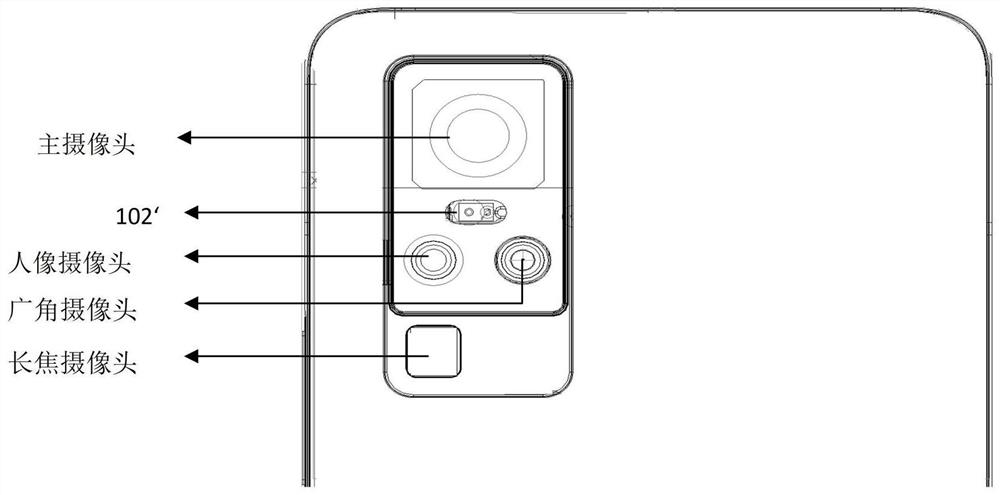
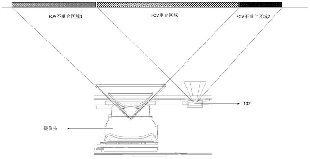
[0002] With the continuous development of the photography function of mobile phones, the number of cameras also increases. Since each camera has an auto-focus function, a focus sensor 102' is set separately to pass through the focus sensor 102'. Measure the distance of the object being photographed, however, the focus sensor 102' is set separately, such as figure 1 As shown, because it is set side by side with the camera, it will occupy limited space on the mobile phone, and its optical axis is not consistent with the camera, so it is impossible to accurately calculate the focus point. In some special angles, such as figure 2 As shown, there will be two non-overlapping areas, and the focus sensor 102' cannot be used to assist the camera to focus in the non-overlapping areas, which greatly affects the user experience

Method used


Image

  • Camera module and electronic equipment
  • Camera module and electronic equipment
  • Camera module and electronic equipment

Examples


Embodiment Construction

[0031] Embodiments of the present application will be described in detail below, examples of which are shown in the drawings, in which the same or similar reference numerals denote the same or similar elements or elements having the same or similar functions throughout. The embodiments described below by referring to the figures are exemplary, and are only for explaining the present application, and should not be construed as limiting the present application. Based on the embodiments in this application, all other embodiments obtained by persons of ordinary skill in the art without creative efforts fall within the protection scope of this application.

[0032] The features of the terms "first" and "second" in the description and claims of the present application may explicitly or implicitly include one or more of these features. In the description of the present application, unless otherwise specified, "plurality" means two or more. In addition, "and / or" in the specification ...


PUM


Abstract

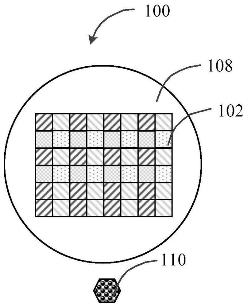
The invention discloses a camera module and electronic equipment. The camera module comprises an image sensor which comprises a substrate, and a plurality of visible light sensing units and a plurality of infrared light sensing units which are uniformly arranged on the substrate; a first light-transmitting structure which covers the image sensor; a laser emitter which is arranged on one side of the image sensor and used for emitting light rays outwards, wherein the infrared light sensing units are used for receiving the light rays reflected by an obstacle and determining the focusing distance according to the light rays. According to the invention, the visible light sensing units and the infrared light sensing units are integrated in the image sensor at the same time, the problem that in the prior art, extra space is needed for arranging a laser focusing sensor can be effectively solved, and moreover, the overlapping degree of the field angles of the visible light sensing units in a laser focusing sensor and the image sensor can be improved; therefore, the accuracy of a focusing point is improved, and the focusing requirement of a user when the camera module is used for shooting is better met.

Description

technical field [0001] The application belongs to the technical field of electronic equipment, and in particular relates to a camera module and an electronic equipment. Background technique [0002] With the continuous development of the photography function of mobile phones, the number of cameras also increases. Since each camera has an auto-focus function, a focus sensor 102' is set separately to pass through the focus sensor 102'. Measure the distance of the object being photographed, however, the focus sensor 102' is set separately, such as figure 1 As shown, because it is set side by side with the camera, it will occupy limited space on the mobile phone, and its optical axis is not consistent with the camera, so it is impossible to accurately calculate the focus point. In some special angles, such as figure 2 As shown, there will be two non-overlapping areas, and the focus sensor 102' cannot be used to assist the camera to focus in the non-overlapping areas, which gre...

Claims


Application Information

Patent Timeline
Patent Type & Authority Applications(China)
IPC IPC(8): H04N5/369H04N5/374H04N5/225H04N5/232
CPCH04N23/54H04N23/671H04N23/57H04N25/704H04N25/76
Inventor 段俊杰
Owner VIVO MOBILE COMM CO LTD
Why Eureka
Try Eureka