Transcritical main shaft system design method based on multi-scale interface regulation and control

A technology of interface control and system design, applied in the direction of geometric CAD, special data processing applications, etc., can solve problems such as the limitation of spindle parameters, the increase of spindle amplitude, and the friction accident of bearing rotors, so as to improve the bearing capacity and stiffness, and improve the dynamic performance. Stability, improve the effect of dynamic pressure effect

Active Publication Date: 2021-06-29
TIANJIN UNIV
View PDF5 Cites 2 Cited by
  • Summary
  • Abstract
  • Description
  • Claims
  • Application Information

AI Technical Summary

Problems solved by technology

However, when the speed of the high-speed spindle is close to or reaches the critical speed, the amplitude of the spindle will rise sharply, which will greatly reduce the dynamic stability of the spindle. In severe cases, the friction of the bearing rotor will cause major accidents
Therefore, in order to ensure the stability of the spindle system, the design of the conventional high-speed hydrodynamic spindle system must strictly limit a series of parameters such as the stiffness, mass, span, and structure of the spindle, so that the design speed is lower than the critical speed
However, in some cases, the parameters of the spindle are limited. For example, if the space is limited, the spindle with a long span and small diameter must be used. At this time, the adjacent speed of the spindle is very low, and the working speed of the spindle is higher than the critical speed. Spindle system design methods no longer apply

Method used


Image

  • Transcritical main shaft system design method based on multi-scale interface regulation and control
  • Transcritical main shaft system design method based on multi-scale interface regulation and control
  • Transcritical main shaft system design method based on multi-scale interface regulation and control

Examples


Embodiment Construction

[0053] In order to ensure the stability of the spindle system, the design of the conventional high-speed hydrodynamic spindle system must strictly limit a series of parameters such as the stiffness, mass, span, and structure of the spindle, so that the design speed is lower than the critical speed. However, when the parameters of the spindle are limited and the operating speed of the spindle is higher than the critical speed, the traditional design method of the spindle system is no longer applicable.

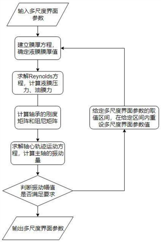
[0054] In order to solve the above problems, the present invention ensures the safety and stability of the spindle system under critical speed conditions by rationally designing the multi-scale interface of the bearing, and proposes a design method for a transcritical spindle system based on multi-scale interface regulation. Transcritical spindle system, a transcritical spindle system is a spindle system that can work normally across critical speeds, and the multi-scale interfac...


PUM


Abstract

The invention belongs to the technical field of main shaft system design, and discloses a transcritical main shaft system design method based on multi-scale interface regulation and control. The method comprises the following steps: giving multi-scale interface parameters; establishing a film thickness equation to obtain a film thickness value of each point of the liquid film; calculating the pressure value of each point of the liquid film to obtain oil film force; calculating a stiffness matrix and a damping matrix of the bearing; solving the axis trajectory motion equation to obtain a spindle vibration quantity; judging whether the spindle vibration quantity meets requirements or not; if not, giving a value interval of the multi-scale interface parameters, resetting the parameters in the given value interval of the multi-scale interface parameters, and performing iterative calculation again; and if yes, outputting the parameters of the multi-scale interface. Through collaborative optimization of deep and shallow cavity interfaces and texture interfaces of the bearing, a functionalized multi-scale interface is formed, the dynamic stability of a main shaft system can be remarkably improved, vibration of the main shaft system is restrained, and the main shaft system can safely and stably work in a critical rotating speed range.

Description

technical field [0001] The invention belongs to the technical field of spindle system design, and in particular relates to a design method for a transcritical spindle system based on multi-scale interface regulation. Background technique [0002] Modern CNC machine tools are developing in the direction of high rigidity and high speed. As the core basic component, the machine tool spindle determines the performance level of the machine tool. However, when the speed of the high-speed spindle is close to or reaches the critical speed, the amplitude of the spindle will increase sharply, which will greatly reduce the dynamic stability of the spindle. In severe cases, the friction of the bearing rotor will cause major accidents. Therefore, in order to ensure the stability of the spindle system, a series of parameters such as the stiffness, mass, span, and structure of the spindle must be strictly limited in the design of the conventional high-speed hydrodynamic spindle system, so...

Claims


Application Information

Patent Timeline
Patent Type & Authority Applications(China)
IPC IPC(8): G06F30/17
CPCG06F30/17
Inventor 张忠江闫帅林彬崔云鑫邹鸿博门士超王春深
Owner TIANJIN UNIV
Why Eureka
Try Eureka