Spraying device for ceramic design and manufacturing
A spraying device and production technology, which can be applied to ceramic molding machines, manufacturing tools, etc., can solve the problems of false ceramic spraying and affecting the progress of ceramic spraying.
- Summary
- Abstract
- Description
- Claims
- Application Information
AI Technical Summary
Problems solved by technology
Method used
Image
Examples
Embodiment 1
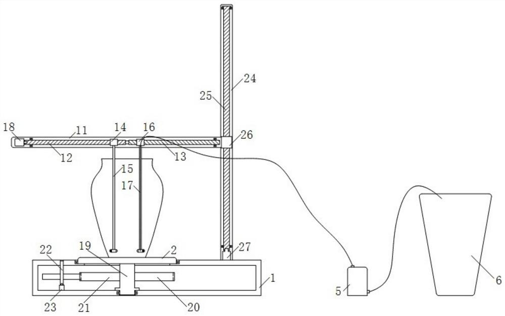
[0059] like figure 1 As shown, the embodiment of the present invention provides a spraying device for ceramic design and production, including a base 1; a disc 2, which is clamped on the base 1, and the upper surface of which is used for placing ceramics; a spraying mechanism, including a sleeve 3; Two spray heads 4, one spray head 4 is facing the inner wall of the ceramic when it is located inside the ceramic for use when spraying glaze inside the ceramic, and the other spray head 4 is facing the outer wall of the ceramic when it is located outside the ceramic for spraying glaze on the outside of the ceramic When used; the flow pump 5, its liquid outlet is connected with the spray head 4 through the connecting assembly, and its liquid inlet is connected with the external glaze cylinder 6 through the connecting pipe; the lateral distance adjustment assembly is connected with the sleeve 3 for When spraying the ceramic inner wall and the ceramic outer wall, adjust the distance b...
Embodiment 2
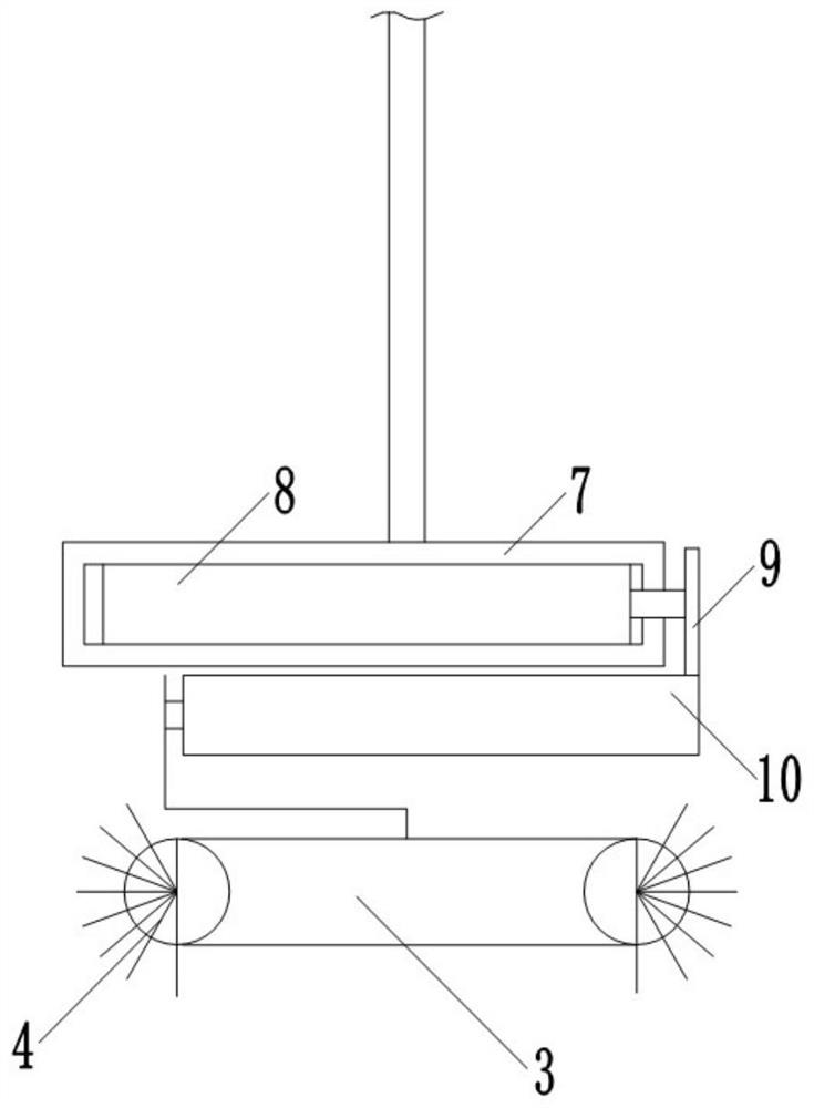
[0063] This embodiment is based on Embodiment 1. The lateral distance adjustment assembly includes two first-level distance adjustment mechanisms for adjusting the distance between the spray heads 4 of the two spraying mechanisms and the ceramic inner wall or the ceramic outer wall, and also includes a first-level distance adjustment mechanism. a mechanism and a secondary distance adjustment mechanism for adjusting the lateral distance between the two spraying mechanisms;
[0064] The first-level distance adjustment mechanism includes a box body 7; a first electric push rod 8, whose outer shell is fixed inside the box body 7, and whose telescopic end is connected with the push plate 9; a second electric push rod 10, whose outer shell is The sliding assembly is slidably connected to the box body 7, the outer casing of the second electric push rod 10 is connected to the push plate 9, and the telescopic end of the second electric push rod 10 is connected to the sleeve 3 through th...
Embodiment 3
[0068] The present implementation is based on the first embodiment. The circumferential rotation mechanism includes a first rotating shaft 19, the upper end of which is fixedly connected to the disk 2, and the lower end of which is connected to the base 1 through a bearing; a driving gear 20 is sleeved and fixed on the base 1. On the side wall of the first rotating shaft 19; the driven gear 21 meshes with the driving gear 20; the second rotating shaft 22 runs through the driven gear 21, and the upper and lower ends of the second rotating shaft 22 are connected to each other through bearings. The base 1 is connected; the second motor 23 is fixed inside the base 1 and its output shaft is connected with the second rotating shaft 22 .
[0069] Further, the longitudinal lifting mechanism includes a longitudinal support plate 24, which is fixed on the upper surface of the base 1; a second screw 25 is connected to the bearing seat fixed on the longitudinal support plate 24 through a b...
PUM
 Abstract
Description
Claims
Application Information
 - R&D
- Intellectual Property
- Life Sciences
- Materials
- Tech Scout
- Unparalleled Data Quality
- Higher Quality Content
- 60% Fewer Hallucinations
Browse by: Latest US Patents, China's latest patents, Technical Efficacy Thesaurus, Application Domain, Technology Topic, Popular Technical Reports.
© 2025 PatSnap. All rights reserved.Legal|Privacy policy|Modern Slavery Act Transparency Statement|Sitemap|About US| Contact US: help@patsnap.com


