
A fire detection tube assembly used in a power distribution cabinet

A technology for fire detection tubes and power distribution cabinets, which can be used in substation/power distribution device shells, fire rescue, etc., and can solve problems such as low fire extinguishing efficiency, loss of electrical components, and impact on fire extinguishing efficiency, and achieve fast fire extinguishing efficiency and wide fire extinguishing range Effect

Active Publication Date: 2022-03-25
烟台凯翔电气有限公司
View PDF0 Cites 0 Cited by
  • Summary
  • Abstract
  • Description
  • Claims
  • Application Information

AI Technical Summary

Problems solved by technology

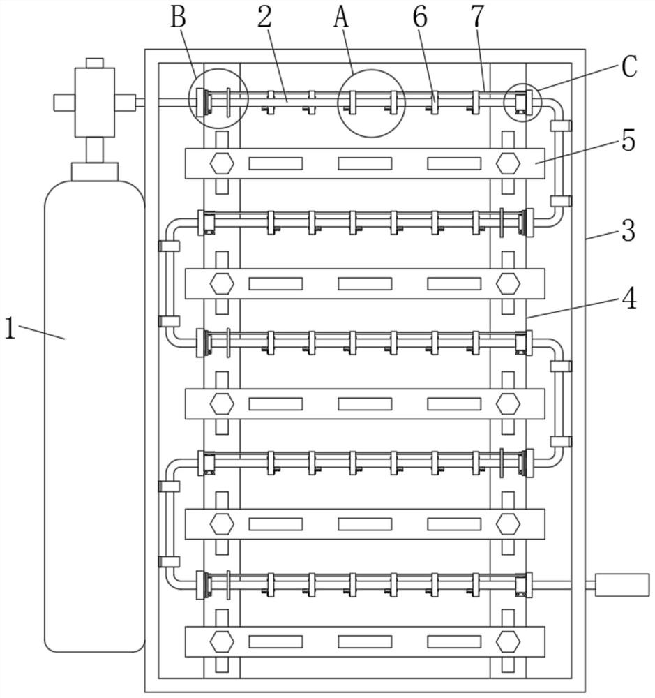
[0004] However, when the existing fire detection tube is in use, when the fire detection tube is softened at the highest heating temperature and blasted off, under the action of high-pressure gas ejection in the fire extinguishing gas tank, the gas is always ejected horizontally to one side, The fire cannot be effectively extinguished until the amount of fire extinguishing gas in the power distribution cabinet is large enough, resulting in low fire extinguishing efficiency, long fire spread time, and large loss of electrical components. However, the disturbance caused the fire extinguishing gas ejected from the blasting hole of the fire detector tube to be unable to directly act on the fire site at the first time, which affected the fire extinguishing efficiency.

Method used


Image

  • A fire detection tube assembly used in a power distribution cabinet
  • A fire detection tube assembly used in a power distribution cabinet
  • A fire detection tube assembly used in a power distribution cabinet

Examples


Embodiment Construction

[0020] The following will clearly and completely describe the technical solutions in the embodiments of the present invention with reference to the accompanying drawings in the embodiments of the present invention. Obviously, the described embodiments are only some, not all, embodiments of the present invention. Based on the embodiments of the present invention, all other embodiments obtained by persons of ordinary skill in the art without making creative efforts belong to the protection scope of the present invention.

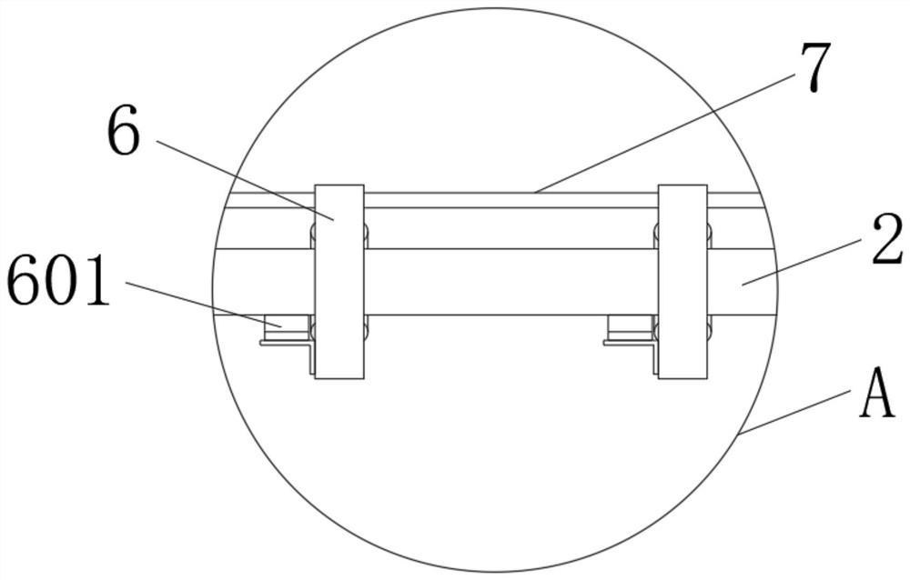
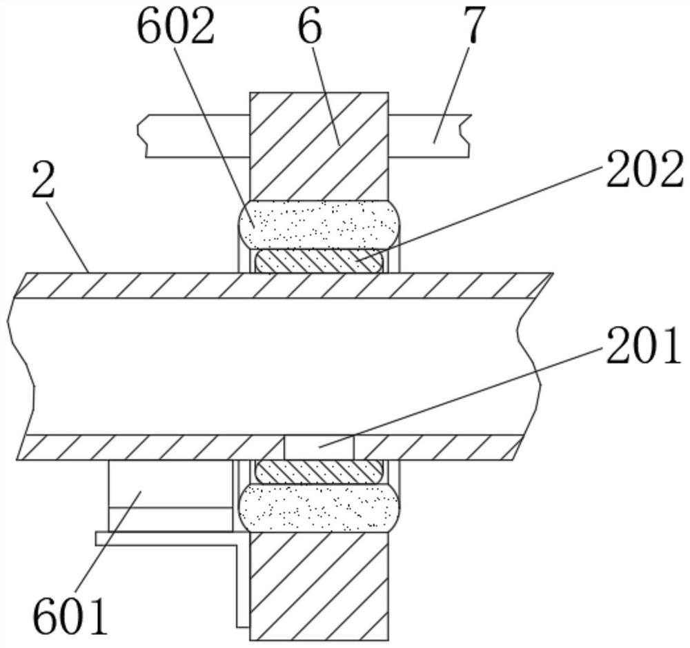
[0021] see Figure 1-6 , a fire detection tube assembly for a power distribution cabinet, including a fire extinguishing gas tank 1 and a fire detection tube 2, the fire extinguishing gas tank 1 is arranged on one side of the power distribution cabinet 3, and both sides of the power distribution cabinet 3 are provided There is a longitudinal mounting plate 4, and several transverse mounting plates 5 are arranged on the longitudinal mounting plate 4. The inlet ...


PUM


Abstract

The invention relates to the technical field of fire extinguishing equipment for power distribution cabinets, and discloses a fire detection tube assembly for power distribution cabinets, including a fire extinguishing gas tank and a fire detection tube. The fire extinguishing gas tank is arranged on one side of the power distribution cabinet. Both sides inside the power distribution cabinet are provided with longitudinal installation plates, and several horizontal installation plates are arranged on the longitudinal installation plates. Access from the top of one side of the distribution cabinet. Through the linkage structure design between the fire detection tube and its upper limit sliding sleeve, cutter and insulating rope, when the electrical components in the power distribution cabinet catch fire, the fire extinguishing gas ejected from the blasting port of the fire detection tube directly acts on the horizontal installation below. The electrical components on the board, compared with the existing method of spraying fire extinguishing gas horizontally to one side after being heated and blasted by the fire detector tube, has a wider fire extinguishing range in a short time, and the fire extinguishing efficiency of the electrical components below is faster, reducing The loss of other electrical components around the fire was burnt out.

Description

technical field [0001] The invention relates to the field of fire extinguishing equipment for power distribution cabinets, in particular to a fire detection tube assembly for power distribution cabinets. Background technique [0002] The power distribution cabinet is a cabinet that integrates electrical components for power distribution. It is also used for power distribution and control of electrical equipment. It provides short-circuit protection when the circuit is overloaded, short-circuited and leaked. In the existing power distribution cabinet It is necessary to set up a fire extinguishing device to prevent the electrical components in the power distribution cabinet from catching fire and causing major losses. [0003] Existing fire extinguishing devices of power distribution cabinets often use fire detection tube components. The fire detection tube is placed near or above the electrical components where the fire source is most likely to occur. The place is softened a...

Claims


Application Information

Patent Timeline
Patent Type & Authority Patents(China)
IPC IPC(8): A62C3/16A62C35/08A62C31/05H02B1/30
CPCA62C3/16A62C35/08A62C31/05H02B1/30
Inventor 周振
Owner 烟台凯翔电气有限公司
Learn More