Modular PCB assembly

A PCB board, modular technology, applied in the field of modular PCB board components, can solve the problems of inconvenient PCB board removal, inconvenient PCB board heat dissipation, affecting PCB board performance, etc., to achieve the effect of easy adjustment

Active Publication Date: 2021-06-25
无棣源通电子科技有限公司
View PDF15 Cites 0 Cited by
  • Summary
  • Abstract
  • Description
  • Claims
  • Application Information

AI Technical Summary

Problems solved by technology

[0002] With the development of technology, people have given more and more functions to PCB boards. As the design of PCB boards becomes more and more complex, in order to standardize the design, a modular layout of multiple PCB boards has appeared. In highly integrated equipment The number of PCB boards is large, but the existing modular PCB board assembly is generally fixed by bolts when fixing multiple PCB boards. This installation method is laborious and laborious, and it is inconvenient when the PCB board needs to be overhauled The staff takes out the PCB board, which increases the labor intensity of the staff. At the same time, the existing modular PCB board assembly is generally inconvenient to realize the heat dissipation on the bottom of the PCB board, and the bottom of the PCB board will easily accumulate more heat during the working process. And the heat at the bottom is not easy to dissipate. If the heat accumulates at the bottom of the PCB board for a long time, it will affect the performance of the PCB board.

Method used


Image

  • Modular PCB assembly
  • Modular PCB assembly
  • Modular PCB assembly

Examples


Embodiment Construction

[0043] Next, the technical solutions in the embodiments of the present invention will be apparent from the embodiment of the present invention, and it is clearly described, and it is understood that the described embodiments are merely embodiments of the present invention, not all of the embodiments. Based on the embodiments of the present invention, there are all other embodiments obtained without making creative labor without making creative labor premises.

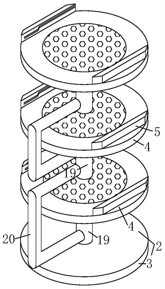
[0044] SeeFigure 1-13 In the embodiment of the present invention, a modular PCB board assembly includes a PCB plate 1, further comprising a mount 2;

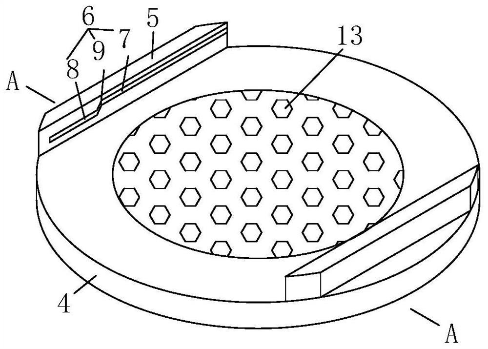
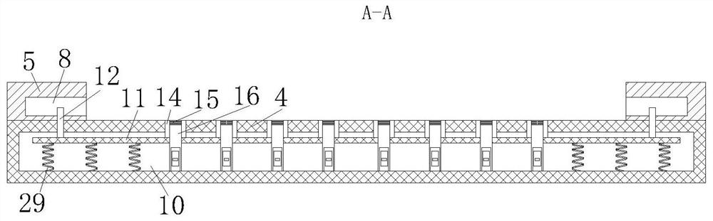
[0045] The mounting seat 2 includes a bottom plate 3 and a carrier plate 4 disposed above the bottom plate 3, and the left and right ends of the carrier plate 4 are fixed to the finite plate 5, and the restricted groove 6 is opened on the restricted groove 6, the end of the PCB plate 1. The portion is fixedly connected to a limiting block 46 that cooperates with the limit slo...


PUM


Abstract

The invention relates to the technical field of PCB assemblies, in particular to a modular PCB assembly, which comprises a PCB and a mounting seat. The mounting seat comprises a bottom plate and a carrying plate arranged above the bottom plate, the left end and the right end of the carrying plate are fixedly connected with limiting plates, limiting grooves are formed in the limiting plates, and the end of the PCB is fixedly connected with limiting blocks matched with the limiting grooves. The limiting groove comprises a first open groove and a positioning groove, the first open groove and the positioning groove are connected through a communication groove, a containing cavity is formed in the carrying plate, a movable plate is elastically connected into the containing cavity, a fixing rod is fixedly connected to the upper end of the movable plate, one end of the fixing rod penetrates through the side wall of the containing cavity and is located in the positioning groove, heat dissipation holes are formed in the carrying plate, and a side plate is fixedly connected to the movable plate. The PCB can be conveniently installed, and meanwhile the heat dissipation effect on the PCB in the working process can be conveniently achieved.

Description

Technical field [0001] The present invention relates to the technical field of PCB board assemblies, and in particular, a modular PCB board assembly. Background technique [0002] With the development of technology, people have given the PCB board increasing function. As the PCB board is more complex, in order to standardize design, the modular layout of multiple PCB boards appears, in the highly integrated equipment There are many quantities of the PCB board, but the existing modular PCB board components are generally fixed by bolts when implementing multiple PCB boards. This installation method is laborious, and it is inconvenient to repair the PCB board. The staff takes out the PCB board, increasing the labor intensity of the staff, and the existing modular PCB board assembly is generally inconvenient to achieve heat dissipation on the bottom of the PCB board, and the PCB board will easily accumulate more heat during the working process. And the amount of heat at the bottom is...

Claims


Application Information

Patent Timeline
Patent Type & Authority Applications(China)
IPC IPC(8): H05K7/14H05K7/20
CPCH05K7/1402H05K7/20145H05K7/20281H05K7/20272H05K7/2039
Inventor 陈龙李佳乐容富强
Owner 无棣源通电子科技有限公司
Why Eureka
Try Eureka