Eureka AIR delivers breakthrough ideas for toughest innovation challenges, trusted by R&D personnel around the world.

Short-exposure high-speed surface scanning rigid splicing microscopic imaging system and method

A micro-imaging, short-exposure technology, applied in microscopes, optics, optical components, etc., can solve the problem of consuming large computing power and achieve the effect of low-destructive scanning, high-speed and high-precision destructive scanning

Active Publication Date: 2021-06-25
SHANGHAI JIAO TONG UNIV
View PDF6 Cites 2 Cited by
  • Summary
  • Abstract
  • Description
  • Claims
  • Application Information

AI Technical Summary

Problems solved by technology

Computer memory consumption increases as the number of images increases, and pairwise matching of images consumes a lot of computer computing power

Method used


Image

  • Short-exposure high-speed surface scanning rigid splicing microscopic imaging system and method
  • Short-exposure high-speed surface scanning rigid splicing microscopic imaging system and method
  • Short-exposure high-speed surface scanning rigid splicing microscopic imaging system and method

Examples


Embodiment 1

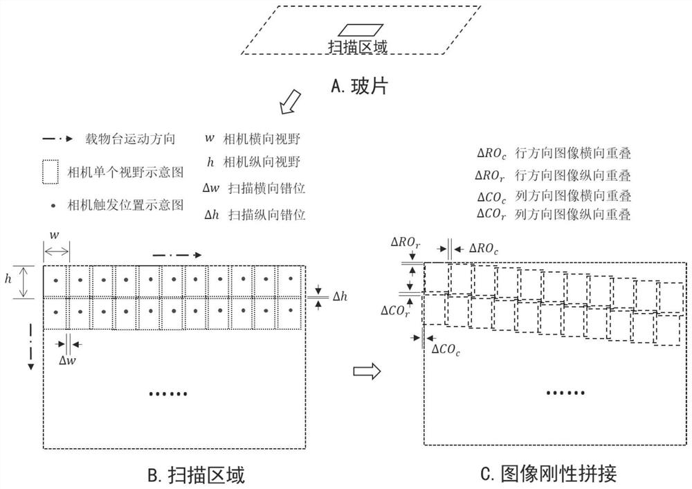
[0056] The short-exposure high-speed surface-scan rigid mosaic microscopic imaging system provided according to the present invention includes a joint anti-distortion imaging system, a synchronous control push-broom system, and an image rigid mosaic algorithm;

[0057] The joint anti-distortion imaging system includes an objective lens, an imaging tube lens, and an image processing algorithm module, and adopts the joint anti-distortion optical design of the objective lens and the imaging tube lens, as well as an image processing algorithm module, so that the edge distortion of the microscopic image is smaller than the preset pixel value;

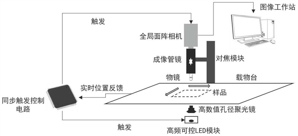
[0058] The synchronous control push-broom system includes a stage, a focusing module, a global shutter area array camera, an LED module, and a synchronous trigger control circuit;

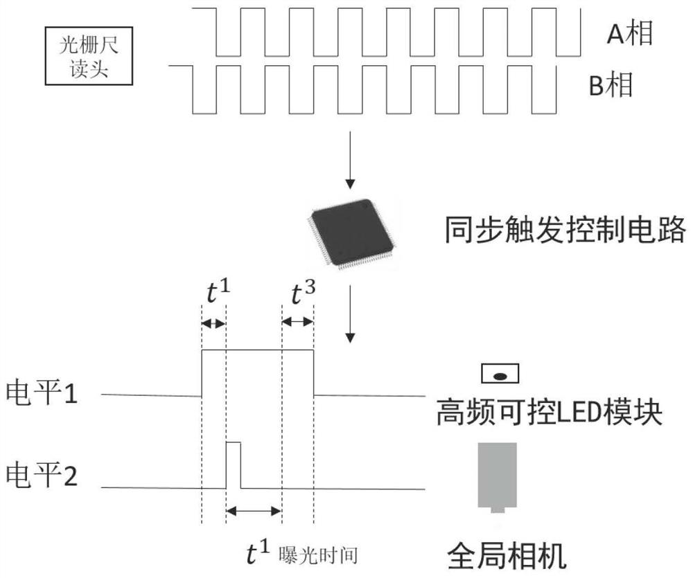
[0059] When the sample on the stage moves to the initial position, the synchronous trigger control circuit first triggers the LED module to maintain high brightne...

Embodiment 2

[0095] Embodiment 2 is a preferred example of Embodiment 1, and this embodiment provides a short-exposure high-speed surface-scanning rigid mosaic microscopic imaging device.

[0096] Such as figure 1 As shown, the device of the present invention includes a joint anti-distortion imaging system, a synchronous control push-broom system and an image rigid mosaic algorithm, wherein the joint anti-distortion imaging system includes an objective lens, an imaging tube lens and an image processing algorithm module. Specifically, the objective lens is 40X, numerical aperture N.A=0.95, focal length of imaging tube lens 153mm, image edge distortion processing algorithm is two-dimensional segmented linear fitting. Synchronous control push-broom system, including high-precision stage, high-precision focusing module, high-sensitivity global shutter area array camera, high-frequency controllable LED module, and synchronous trigger control circuit. Specifically, the minimum resolution of the ...


PUM


Abstract

The invention provides a short-exposure high-speed surface scanning rigid splicing microscopic imaging system and method. The system comprises a combined distortion elimination imaging system, a synchronous control push-broom system and an image rigid splicing algorithm. The combined distortion elimination imaging system comprises an objective lens, an imaging tube lens and an image processing algorithm module, and an objective lens and imaging tube lens combined distortion elimination optical design and an image processing algorithm module are adopted to realize that microscopic image edge distortion is smaller than a preset pixel value; and the synchronous control push-broom system comprises an objective table, a focusing module, a global fast door area-array camera, an LED module and a synchronous trigger control circuit. And the image rigid splicing algorithm executes online splicing operation in a high-speed push-broom process. According to the invention, high-speed distortionless scanning splicing under different multiplying powers is realized, and the system can be widely applied to the microscopic scanning fields of biology, medicine and the like.

Description

technical field [0001] The invention relates to the technical fields of microscanning, image mosaicing and precision control, in particular to a short-exposure high-speed surface scanning rigid mosaic microscopic imaging system and method. Background technique [0002] Optical microscope is an essential tool for biologists to do research and explore the mysteries of life. People have used the eyepieces of light microscopes to understand and analyze the intricate structure and morphology of cells on glass slides. In recent years, digital scanning microscopes can quickly scan and image the entire slide with full information, turning traditional physical slides into a new generation of digital virtual slices, enabling slide scientific research, fluorescence preservation, digital storage, clinical teaching, and remote communication , Collective film reading and other functional purposes. [0003] The microscopic imaging optical system includes objective lens and imaging tube l...

Claims


Application Information

Patent Timeline
Patent Type & Authority Applications(China)
IPC IPC(8): G02B21/36
CPCG02B21/365G02B21/367
Inventor 程昊谷朝臣关新平吴开杰
Owner SHANGHAI JIAO TONG UNIV
Why Eureka
Eureka Blog
Learn More