
Building tile automatic level detection and correction device

A technology for level detection and construction. It is applied in the field of automatic level detection and correction devices for building tiles. It can solve the problems of uneven tile correction, inaccurate detection results, labor-intensive and other problems, so as to achieve firm paste and accurate detection results. , labor-saving effect

Inactive Publication Date: 2021-06-25
合肥疃钢脚手架租赁有限公司
View PDF0 Cites 0 Cited by
  • Summary
  • Abstract
  • Description
  • Claims
  • Application Information

AI Technical Summary

Problems solved by technology

[0006] Aiming at the deficiencies of the prior art, the present invention provides an automatic level detection and correction device for architectural tiles, which has the advantages of automatically detecting the level of tiles and correcting uneven tiles in stages, and solves the problem of laying and pasting tiles in building manufacturing, all of which are done manually. To flatten the tiles, or to flatten the tiles with an ordinary flattener, there is no electromechanical equipment that can automatically detect whether the tiles are laid horizontally, and there is no way to correct the uneven tiles. Traditional laying Due to the lack of hammering and vibration between the tiles and the cement in the way of tiles, it is easy to make the adhesion between the tiles and the cement not strong enough, which will further lead to hollow or falling off of the interior of the tiles after pasting. However, through traditional manual inspection Whether the tiles are laid flat, labor-intensive, and the detection results are not accurate enough, which does not conform to the actual situation.

Method used


Image

  • Building tile automatic level detection and correction device
  • Building tile automatic level detection and correction device
  • Building tile automatic level detection and correction device

Examples


Embodiment Construction

[0029] The following will clearly and completely describe the technical solutions in the embodiments of the present invention with reference to the accompanying drawings in the embodiments of the present invention. Obviously, the described embodiments are only some, not all, embodiments of the present invention. Based on the embodiments of the present invention, all other embodiments obtained by persons of ordinary skill in the art without making creative efforts belong to the protection scope of the present invention.

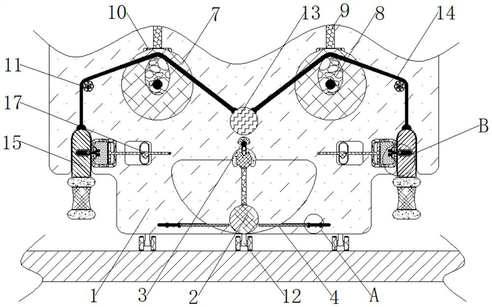
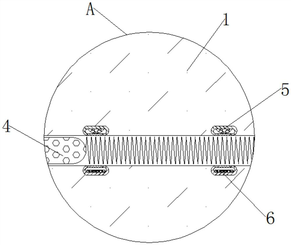
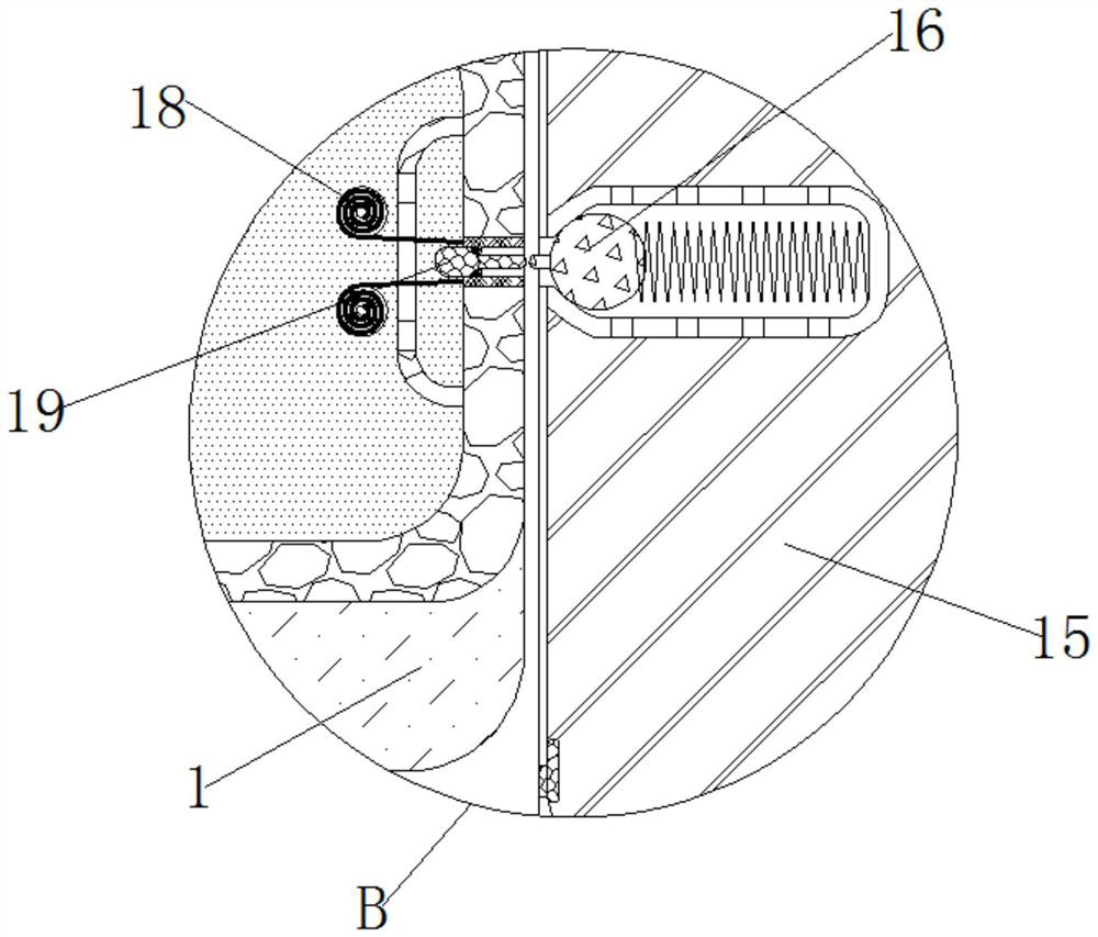
[0030] see Figure 1-4 , an automatic level detection and correction device for building ceramic tiles, comprising a housing 1, the inside of the housing 1 is movably connected with a horizontal rod 2, and the inside of the housing 1 is movably connected with a limit assembly 3, the limit assembly 3 is mainly composed of an electromagnet 1, spring 1, and a limit iron. The inside of the shell 1 is fixedly connected to an electromagnet, and the outside of the el...


PUM


Abstract

The invention relates to the technical field of electromechanical equipment, and discloses a building tile automatic level detection and correction device which comprises a shell. A horizontal rod is movably connected in the shell, a limiting assembly is movably connected in the shell, a trigger rod is slidably connected in the shell, and a direct illuminating lamp is fixedly connected in the shell. The interior of the shell is fixedly connected with a photosensitive assembly, the interior of the shell is rotatably connected with an end face gear, and the exterior of the end face gear is fixedly connected with an eccentric wheel. Through mutual cooperative use of the shell, the horizontal rod, the limiting assembly, the trigger rod, the direct illuminating lamp and the photosensitive assembly, the device is placed on the surface of a to-be-detected tile, through automatic operation of the mechanisms, the effect of automatically detecting the levelness of the tile can be achieved, the detection result is further more accurate, and meanwhile, when the tiles are uneven, the follow-up correcting mechanism can be triggered to operate, labor is saved, and the device is more suitable for actual use.

Description

technical field [0001] The invention relates to the technical field of electromechanical equipment, in particular to an automatic level detection and correction device for architectural tiles. Background technique [0002] With the continuous improvement of people's living standards, people's demand for electromechanical equipment in daily life is increasing, and electromechanical equipment is widely used in various fields such as production, food, and construction. [0003] Electromechanical equipment is also used in many aspects in building manufacturing, and tile paving in building manufacturing is done by manually flattening tiles, or flattening tiles by ordinary flatteners, and none of the electromechanical equipment can do it. Automatically detect whether the tiles are laid horizontally, and there is no way to correct the uneven tiles. The traditional way of laying tiles is easy to cause insufficient adhesion between the tiles and the cement due to the lack of hammerin...

Claims


Application Information

Patent Timeline
Patent Type & Authority Applications(China)
IPC IPC(8): G01C9/00G01C9/02G01C15/00G01B11/30E04F21/22
CPCE04F21/22G01B11/30G01C9/00G01C9/02G01C15/008
Inventor 付振兴
Owner 合肥疃钢脚手架租赁有限公司
Learn More