
Automatic welding device for welding bonding pad

An automatic welding and welding pad technology, which is applied in welding equipment, auxiliary welding equipment, welding/cutting auxiliary equipment, etc., can solve the problems of low production efficiency and low processing precision, achieve convenient implementation, simple overall structure, and improve welding precision and productivity effects

Pending Publication Date: 2021-06-25
广西华盈智能科技有限公司
View PDF8 Cites 0 Cited by
  • Summary
  • Abstract
  • Description
  • Claims
  • Application Information

AI Technical Summary

Problems solved by technology

[0003] The present invention improves the problems of low processing precision and low production efficiency by using manual welding for the processing and welding of existing parts, and provides automatic welding equipment for welding pads, including a machine base, which is provided with a rotary indexable A turntable, the turntable is provided with a plurality of fixed seats distributed around its circumference at intervals for placing materials, and the base is provided with a first feeding mechanism and a second feeding mechanism for transferring materials toward the fixed seats And a welding mechanism for welding materials in the fixed seat is provided, a manual loading and unloading station is provided between the first feeding mechanism and the second feeding mechanism, the manual loading and unloading station, the The first feeding mechanism, the welding mechanism, and the second feeding mechanism are arranged at intervals around the turntable in turn and are respectively located on the side of the fixed seat that has been rotated in place.

Method used


Image

  • Automatic welding device for welding bonding pad
  • Automatic welding device for welding bonding pad
  • Automatic welding device for welding bonding pad

Examples


Embodiment Construction

[0024] In order to make the technical problems, technical solutions and beneficial effects solved by the present application clearer, the present application will be further described in detail below in conjunction with the accompanying drawings and embodiments. It should be understood that the specific embodiments described here are only used to explain the present application, not to limit the present application.

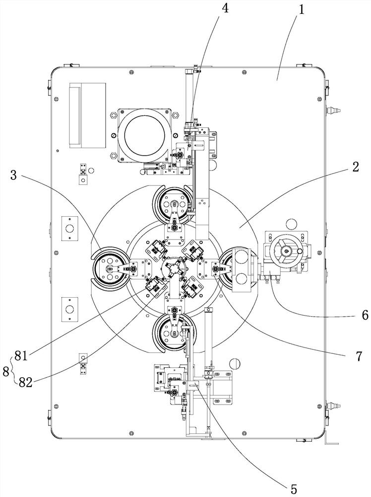
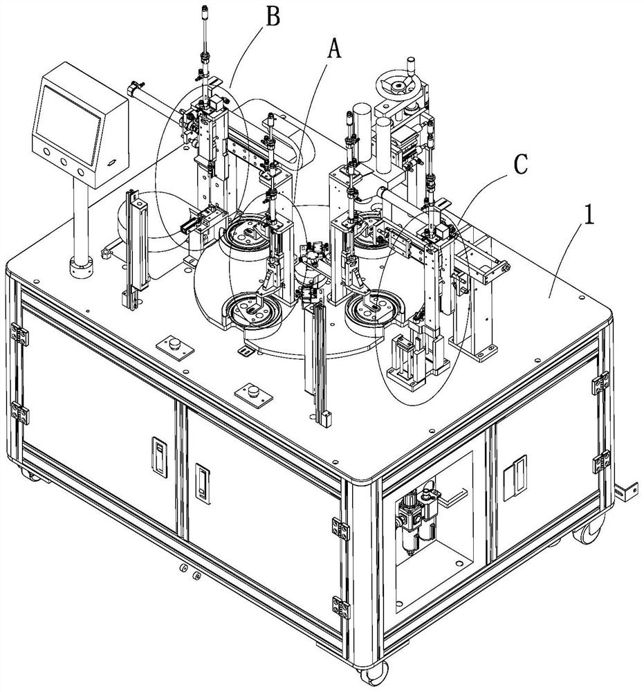
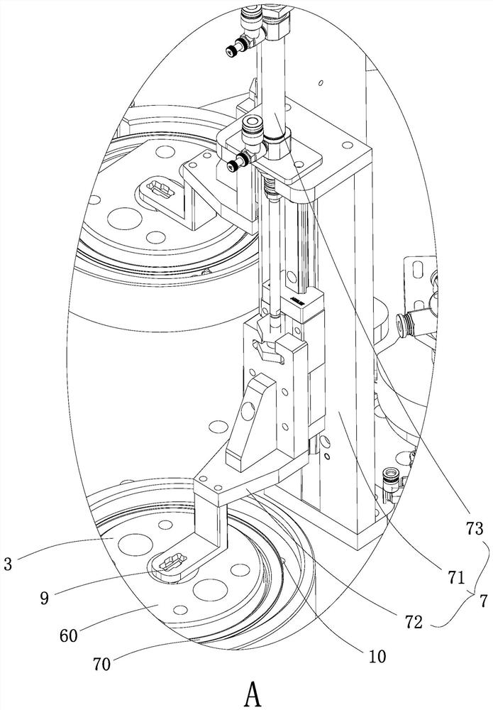
[0025] Such as Figure 1-8 The shown automatic welding equipment for welding pads includes a base 1, on which a turntable 2 that can be rotated on a horizontal plane is provided, and on the turntable 2 there are multiple A fixed seat 3 for placing materials, the base 1 is provided with a first feeding mechanism 4 and a second feeding mechanism 5 for transferring materials toward the fixed seat 3 and is provided with a material for welding inside the fixed seat 3 The material welding mechanism 6, the first feeding mechanism 4, the welding mechanism 6 and the seco...


PUM


Abstract

The invention discloses an automatic welding device for welding a bonding pad. The automatic welding device comprises a machine base, wherein a rotary disc capable of rotating in an indexing mode is arranged on the machine base; a plurality of fixing bases which are distributed around the peripheral side of the rotary disc at intervals and are used for placing materials are arranged on the rotary disc; a first feeding mechanism and a second feeding mechanism which are used for transferring the materials towards the fixing bases and a welding mechanism used for welding the materials in the fixing bases are arranged on the machine base; a manual feeding and discharging station is arranged between the first feeding mechanism and the second feeding mechanism; and the manual feeding and discharging station, the first feeding mechanism, the welding mechanism and the second feeding mechanism are sequentially arranged around the rotary disc at intervals and are located on one sides of the fixing bases which rotate in place respectively. According to the automatic welding device, the manual feeding and discharging station, the first feeding mechanism, the welding mechanism and the second feeding mechanism are arranged around the peripheral side of the rotary disc at intervals, so that automatic welding of the bonding pad and a pressing block is realized, the welding precision and the production efficiency are improved, the overall structure is simple, and the implementation is convenient.

Description

【Technical field】 [0001] The present application relates to the technical field of automation equipment, in particular to automatic welding equipment for welding pads. 【Background technique】 [0002] Most of the existing parts are processed and welded by manual assembly, which has the problems of low processing precision and low production efficiency. 【Content of invention】 [0003] The present invention improves the problems of low processing precision and low production efficiency by using manual welding for the processing and welding of existing parts, and provides automatic welding equipment for welding pads, including a machine base, which is provided with a rotary indexable A turntable, the turntable is provided with a plurality of fixed seats distributed around its circumference at intervals for placing materials, and the base is provided with a first feeding mechanism and a second feeding mechanism for transferring materials toward the fixed seats And a welding me...

Claims


Application Information

Patent Timeline
IPC IPC(8): B23K37/04B23K37/047
CPCB23K37/04B23K37/047B23K37/0435
Inventor 梁雪梅
Owner 广西华盈智能科技有限公司
Learn More