Integrated clamping and fastening mechanism for optical lens
A technology of optical lens and clamping mechanism, which is applied in the direction of workpiece clamping devices, hand-held tools, manufacturing tools, etc., can solve the problems of optical lens clamping and clamping, so as to increase the force, reduce the cost of measurement, simplify The effect of the measurement process
- Summary
- Abstract
- Description
- Claims
- Application Information
AI Technical Summary
Problems solved by technology
Method used
Image
Examples
Embodiment 1
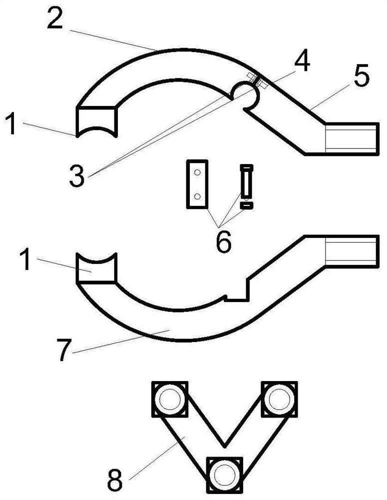
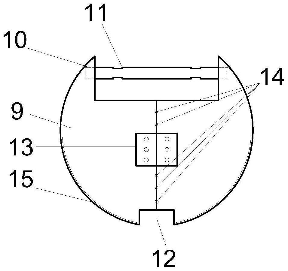
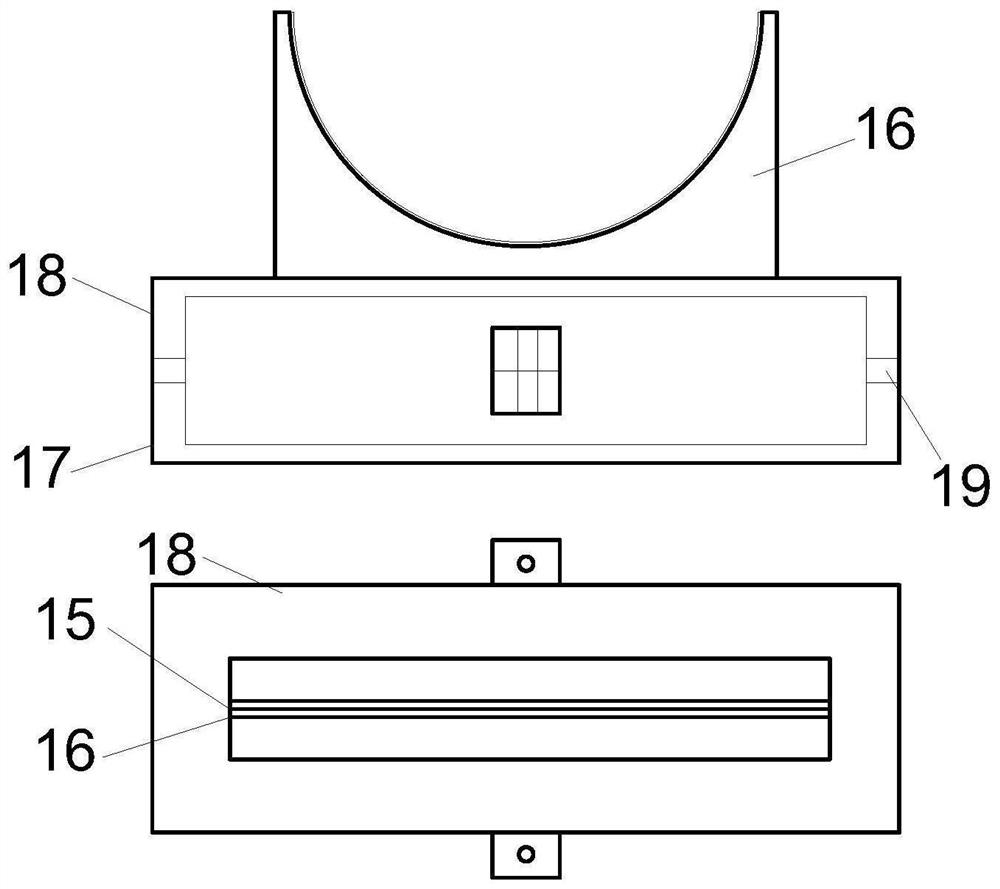
[0035]In this embodiment, an integrated clamping and clamping mechanism for an optical lens, the main structure includes: a clamping arm, a disc mechanism, a frame mechanism 16, a base, and a knob unit; the clamping arm and The disc mechanism is movably connected, and the disc mechanism rests on the card frame mechanism 16, which is fixedly connected with the base, and the knob unit is installed in the base; the operator operates the rear end of the clamp arm with three fingers to open the front end of the clamp arm. Open, put the optical lens under test, release your finger and the perspective mirror is clamped, then place the disc mechanism of the clamping arm on the clamp mechanism, rotate the magnet knob to magnetically lock the disc mechanism. Such as Image 6 shown.
[0036] In this embodiment, the clamping arm and the knob unit are used for clamping and constraining, without artificially clamping the test piece, avoiding the risk that the surface of the test piece is e...
Embodiment 2
[0038] This embodiment is basically the same as Embodiment 1, especially in that:
[0039] Among them, through figure 1 It can be seen that the clamping arm comprises two upper clamping arms and a lower clamping arm and a sleeve 8, and the upper clamping arm comprises: a clamping head 1, an upper clamping arm front part 2, threaded holes 3. The groove 4, the rear part of the upper clamping arm 5, the connection unit 6; the lower clamping arm includes: a clamping head 1, and the lower clamping arm 7. The connection method is as follows: a clamping head 1 is installed at one end of the front part 2 of the upper clamping arm, and the clamping head 1 is shaped as a rectangular parallelepiped with one side of the arc, and the edge of the tested part is realized through the recess part on it. For clamping, the other end is welded on the front part 2 of the upper clamping arm; a groove 4 and a threaded hole 3 are opened in the middle of the other side of the front part 2 of the uppe...
PUM
 Abstract
Description
Claims
Application Information
 - R&D
- Intellectual Property
- Life Sciences
- Materials
- Tech Scout
- Unparalleled Data Quality
- Higher Quality Content
- 60% Fewer Hallucinations
Browse by: Latest US Patents, China's latest patents, Technical Efficacy Thesaurus, Application Domain, Technology Topic, Popular Technical Reports.
© 2025 PatSnap. All rights reserved.Legal|Privacy policy|Modern Slavery Act Transparency Statement|Sitemap|About US| Contact US: help@patsnap.com


