
Sludge drying and incinerating device and sludge incinerating method thereof

A sludge drying and incineration device technology, applied in the combustion method, incinerator, combustion type and other directions, can solve the problems of hot water use end, inability to accurately control furnace temperature, inability to fully absorb heat, etc., to achieve stable absorption Heat, eliminate the effect of excessive furnace temperature fluctuations

Active Publication Date: 2021-06-18
ZHEJIANG XIANCHUANG ENERGY TECH CO LTD
View PDF14 Cites 1 Cited by
  • Summary
  • Abstract
  • Description
  • Claims
  • Application Information

AI Technical Summary

Problems solved by technology

The general heat recovery device requires a stable heat supply in the furnace. For example, the heat recovery device for heating water has a fixed water supply. If the temperature in the furnace is too high, it will not be able to fully absorb heat. If the water temperature is too low, it will cause the water temperature to be too low, which will affect the use of hot water
Due to the different components of different sludges, the temperature of the furnace cannot be accurately controlled only by controlling the moisture content in the sludge, which is not conducive to energy saving and emission reduction

Method used


Image

  • Sludge drying and incinerating device and sludge incinerating method thereof
  • Sludge drying and incinerating device and sludge incinerating method thereof
  • Sludge drying and incinerating device and sludge incinerating method thereof

Examples


Embodiment Construction

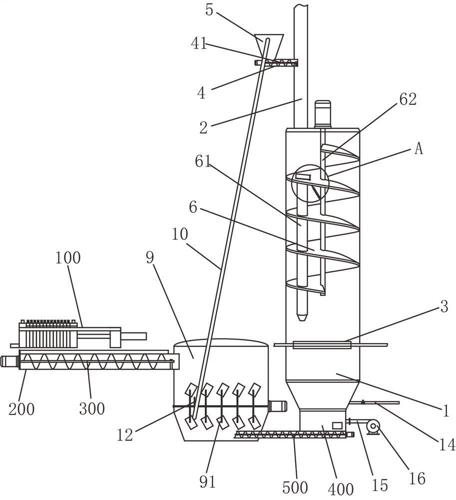
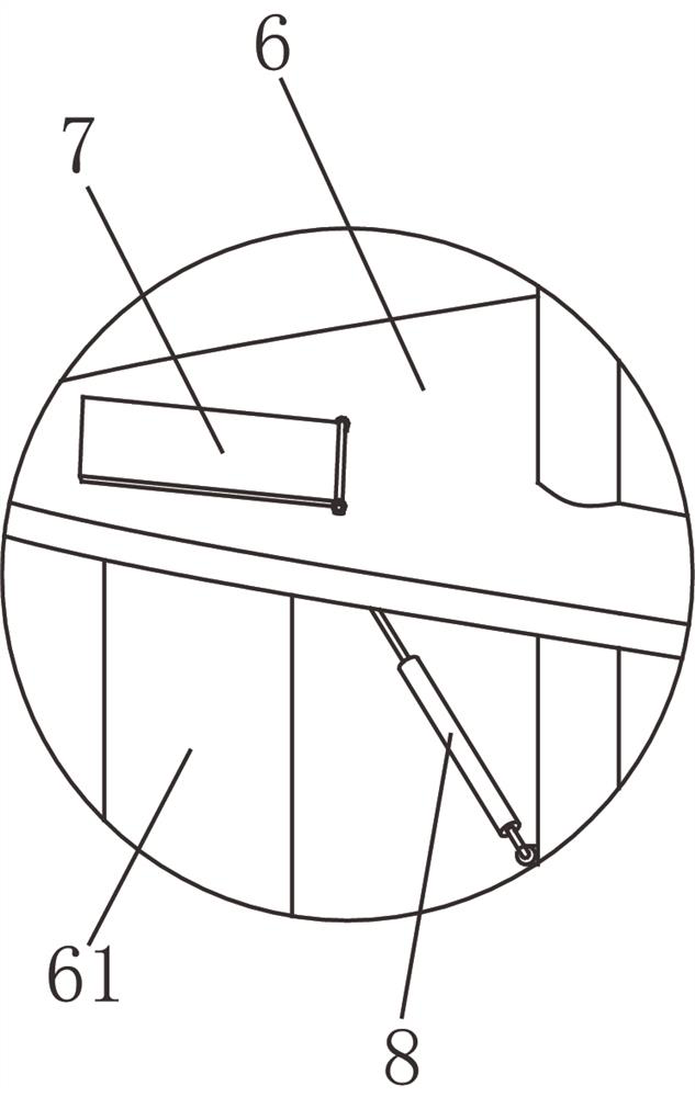
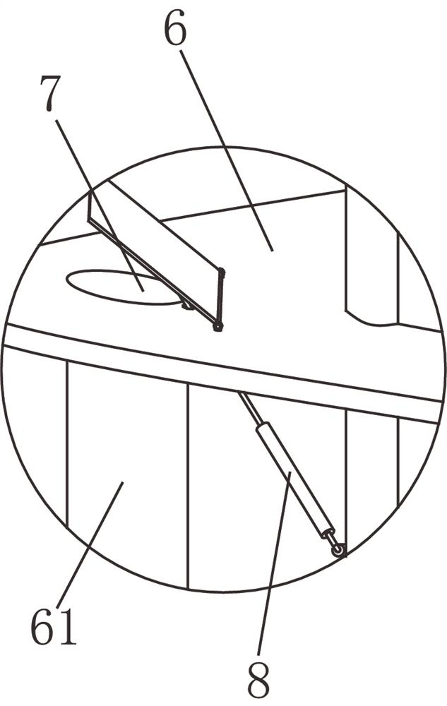
[0023] The present invention will be described in further detail below in conjunction with accompanying drawing and specific embodiment: see Figure 1 to Figure 6 , sludge drying and incineration device, including an incinerator body 1, a vertical smoke exhaust channel 2 is arranged on the top of the incinerator body 1, and a heat recovery device 3 is installed inside the incinerator body 1. In this embodiment, the heat recovery device 3 It is a pipe for heating water. The smoke exhaust passage 2 is connected with a feed hopper 5 through a feed passage 4. A first screw conveyor 41 is arranged in the feed passage 4. A spiral sludge drying slide is arranged on the top of the incinerator body 1. 6, the spiral sludge drying slideway 6 is sealed with the side wall of the incinerator body 1, the spiral sludge drying slideway 6 is provided with a through-through sludge discharge channel 61, and the top of the sludge discharge channel 61 is provided with a warm The control cover 7, th...


PUM


Abstract

The invention discloses a sludge drying and incinerating device and a sludge incinerating method thereof. The sludge drying and incinerating device comprises an incinerator body, a vertical smoke exhaust channel is formed in the top of the incinerator body, a heat recovery device is arranged in the incinerator body in a penetrating mode, a feeding hopper is connected to the smoke exhaust channel through a feeding channel, a first spiral conveyor is arranged in the feeding channel, a spiral sludge drying sliding way is arranged at the top in the incinerator body and matched with the side wall of the incinerator body in a sealed mode, a penetrating and through sludge falling channel is formed in the spiral sludge drying sliding way, and a temperature control cover plate is arranged at the top of the sludge falling channel; the temperature control cover plate is controlled by a temperature control push rod to cover or open the sludge falling channel, so that the temperature in the incinerator body is maintained at a set temperature, the situation that the temperature fluctuation of a hearth is too large due to different sludge components is avoided, the heat recovery device can stably absorb heat, and energy conservation and emission reduction are facilitated.

Description

technical field [0001] The invention belongs to the technical field of sludge incineration devices and methods, in particular to a sludge drying and incineration device and a sludge incineration method thereof. Background technique [0002] With the rapid development of the economy, the amount of urban sewage is gradually increasing, and the construction scale of municipal sewage treatment plants is also expanding, resulting in an increasing output of residual sludge after sewage treatment. At present, the sludge disposal technology can be divided into incineration, landfill, land use and so on. Sludge incineration is recognized as one of the most practical treatment technologies due to its advantages of high reduction, on-site incineration, no need for long-distance transportation, and resource utilization of fly ash. [0003] According to the requirements of standards such as "Technical Specifications for Sludge Incineration Treatment Engineering in Urban Sewage Treatment...

Claims


Application Information

Patent Timeline
Patent Type & Authority Applications(China)
IPC IPC(8): F23G7/00F23G5/04F23G5/44F23G5/46F23G5/50
CPCF23G5/04F23G5/44F23G5/46F23G5/50F23G7/001F23G2206/10F23G2209/12
Inventor 方振明陈勇强柳华桥方斯远
Owner ZHEJIANG XIANCHUANG ENERGY TECH CO LTD
Learn More