Collision energy dissipater structure with low side slope splashing strength and high energy dissipation efficiency

A technology for energy dissipators and slopes, which is applied in water conservancy projects, marine engineering, coastline protection, etc., can solve problems such as damage and the threat of downstream bank slopes, and achieves increased collision energy dissipation, obvious longitudinal opening of the water tongue, and overhang distance. far effect

Pending Publication Date: 2021-06-15
CHANGJIANG RIVER SCI RES INST CHANGJIANG WATER RESOURCES COMMISSION +1
View PDF5 Cites 0 Cited by
  • Summary
  • Abstract
  • Description
  • Claims
  • Application Information

AI Technical Summary

Problems solved by technology

However, the collision of the water tongue in the middle hole has brought about a new atomization problem, especially the collision of the water tongue in the side hole will bring about the problem of high-intensity splashing water that threatens or even destroys the side slope of the pad pond and the downstream bank slope

Method used


Image

  • Collision energy dissipater structure with low side slope splashing strength and high energy dissipation efficiency
  • Collision energy dissipater structure with low side slope splashing strength and high energy dissipation efficiency
  • Collision energy dissipater structure with low side slope splashing strength and high energy dissipation efficiency

Examples


Embodiment Construction

[0025] The technical solutions in the embodiments of the present invention are clearly and completely described below in conjunction with the accompanying drawings in the embodiments of the present invention. Obviously, the described embodiments are only part of the embodiments of the present invention, not all of them. Based on the embodiments of the present invention, all other embodiments obtained by persons of ordinary skill in the art without making creative efforts belong to the protection scope of the present invention.

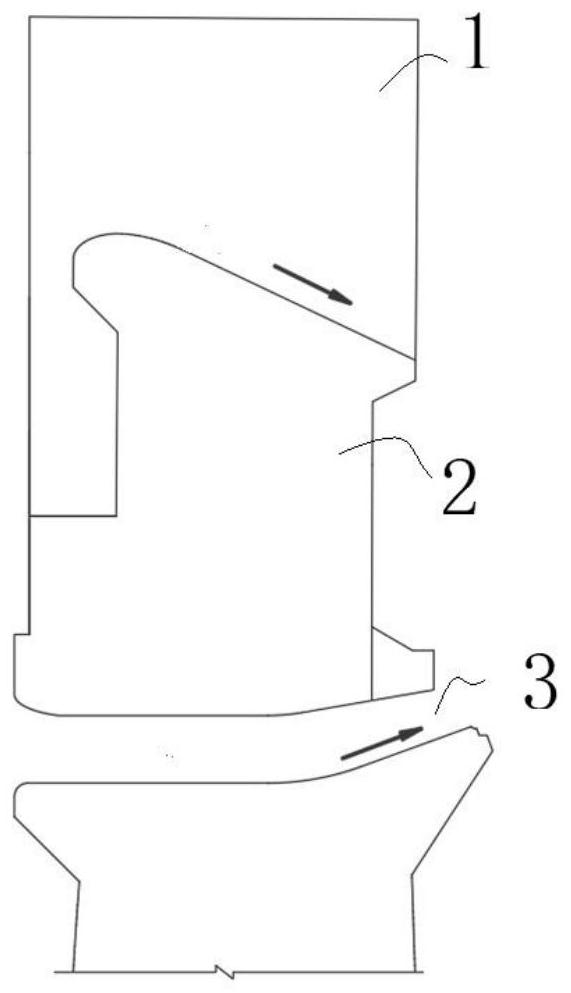
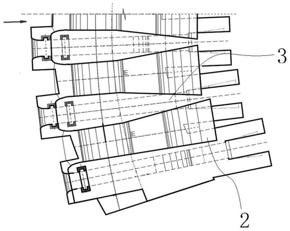
[0026] see image 3 and Figure 4 , the embodiment of the present invention provides a collision energy dissipation structure with low slope water splash strength and high energy dissipation efficiency, including surface holes 2 and middle holes 3 arranged on the dam body from top to bottom for flood discharge, such as figure 1 and Figure 4 As shown, the surface holes 2 and middle holes 3 are located on different horizontal planes of the dam body an...


PUM


Abstract

The invention provides a collision energy dissipater structure with low side slope splashing strength and high energy dissipation efficiency. The collision energy dissipater structure comprises surface holes, middle holes and baffling piers, wherein the surface holes and the middle holes are formed in a dam body from top to bottom and used for flood discharge, and the baffling piers are arranged at the gate pier positions, located on the outer sides of outlet tail ends of the surface holes, of the side edge of the dam body, and the baffling piers are used for deflecting water flow on the outer sides of the surface holes into a flood discharge center line, so that the side slope splashing strength caused by air collision of water is reduced, meanwhile, the water flow depth of the inner sides of the surface holes where the baffling piers are located is increased, and the baffling piers are further used for dispersing the water flow, increasing the effective width of the water flow at outlets of the surface holes and increasing the effective area of the water flow falling into a plunge pool. According to a collision energy dissipater structure with the low side slope splashing strength and high energy dissipation efficiency, the thickness and the position of a side hole collision nappe are changed through the reasonably designed baffling piers, so that a small jet flow which is light and thin on the side and long in jet trajectory length collides with a large main jet flow, the splashing strength of the side holes is reduced, thick and heavy water flows on the inner side collide with one another, the efficiency effect is improved, the collision energy dissipation effect is enhanced, and the side slope splashing strength is relieved as well.

Description

technical field [0001] The invention relates to the field of water conservancy engineering energy dissipators, in particular to a collision energy dissipator structure with low slope splash strength and high energy dissipation efficiency. Background technique [0002] The most common form of flood discharge and energy dissipation for high arch dams in canyon areas is the energy dissipation form of dam body surface holes, middle holes combined with water cushion ponds (such as figure 1 and figure 2 As mentioned above), it is also an efficient and economical energy dissipation method, which has been confirmed by the successful application of a large number of practical projects. In a large number of high arch dams built in recent years, most of the flood discharge and energy dissipation methods adopt the combined energy dissipation scheme mainly in the form of overhanging flow in the middle of the dam body surface and water cushion pond. This is because the scouring of the ...

Claims


Application Information

Patent Timeline
Patent Type & Authority Applications(China)
IPC IPC(8): E02B8/06
CPCE02B8/06
Inventor 翟静静翁永红姜治兵胡清义杨青远王英奎侯冬梅曹去修李静杨伟
Owner CHANGJIANG RIVER SCI RES INST CHANGJIANG WATER RESOURCES COMMISSION
Why Eureka
Try Eureka