Soil drilling equipment suitable for slope engineering
A drilling equipment and engineering technology, applied in application, planting method, excavation/covering of trenches, etc., can solve problems such as inconvenient drilling, save time, avoid soil splashing, and facilitate cleaning
- Summary
- Abstract
- Description
- Claims
- Application Information
AI Technical Summary
Problems solved by technology
Method used
Image


Examples
Embodiment 1
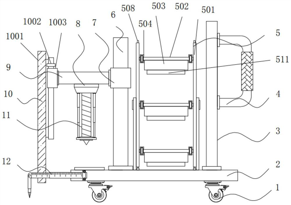
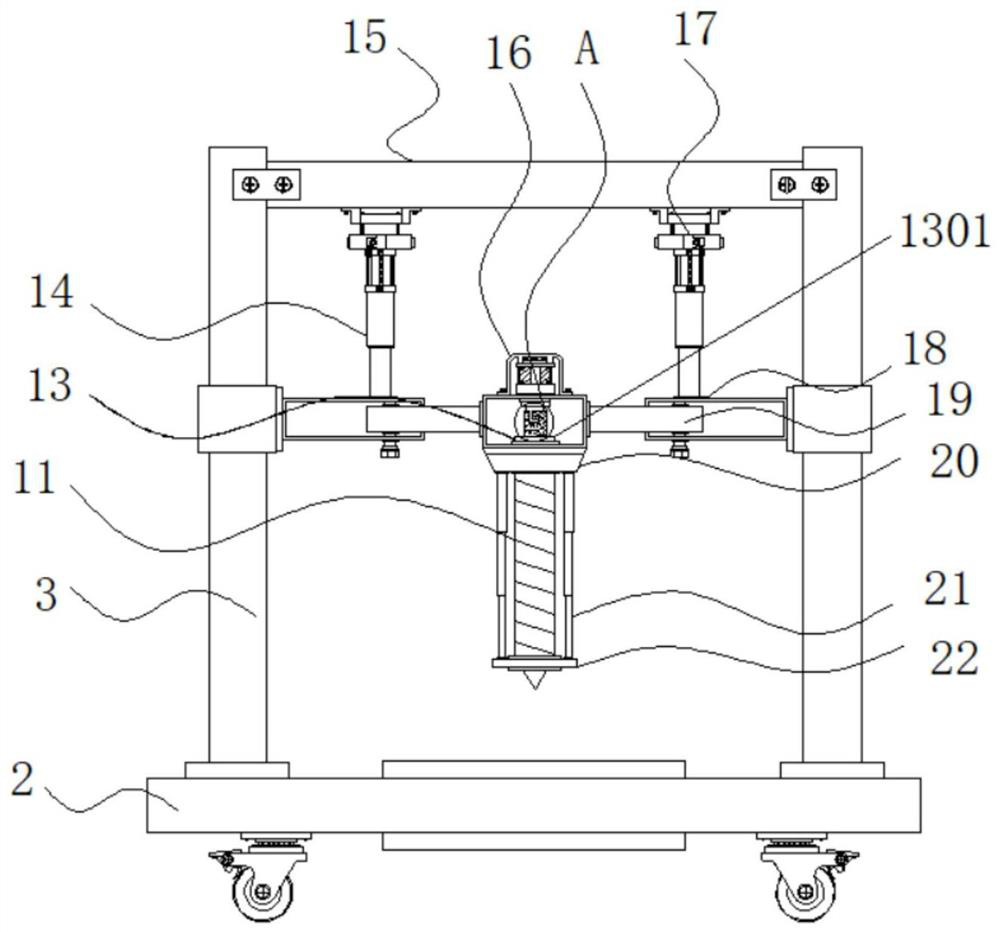
[0039] Example 1: see Figure 1-8 , a soil drilling equipment suitable for slope engineering, including a roller 1 and a base 2, four sets of rollers 1 are fixedly connected to the four corners of the bottom end of the base 2, and a vertical rod 3 is fixedly connected to one side of the top of the base 2, One side of the vertical rod 3 is fixedly connected with a handle 4, one side of the vertical rod 3 is provided with a placement structure 5, the top of the base 2 is fixedly connected with two sets of fixed rods 6, and the outer movable sleeve of the fixed rod 6 is connected with a sleeve block 7, One side of the sleeve block 7 is fixedly connected with a support rod 9, one side of the support rod 9 is fixedly connected with a protective structure 10, one end of the support rod 9 is provided with a drill bit 11, and one side of one end of the base 2 is fixedly connected with a measuring structure 12, the drill bit The top of the 11 is provided with a mounting structure 13, a...
Embodiment 2
[0044] Example 2: The placement structure 5 is composed of two side rotating plates 501, a placement plate 502, a placement box 503, a chute 504, a slider 505, a placement slot 506 and two side support plates 507, the support plates 507 are fixedly connected to the base 2, the rotating plate 501 is rotatably connected to the support plate 507, three sets of placing plates 502 are arranged between the rotating plates 501 on both sides, and a placing box 503 is fixedly connected to the bottom of the placing plate 502. Two sets of sliding blocks 505 are fixedly connected to both sides of the 502 , the top of the placing plate 502 is provided with eight sets of placing grooves 506 , and the rotating plate 501 is rotatably connected with six sets of sliding grooves 504 .
[0045] The placement grooves 506 are equally spaced at the top of the placement plate 502 , and the sliding block 505 and the chute 504 are in sliding connection.
[0046] The two ends of the rotating plate 501 a...
Embodiment 3
[0049] Embodiment 3: The protective structure 10 is composed of a protective plate 1001, a limit plate 1002, a fixing block 1003, a clamping block 1004 and a clamping slot 1005. The fixing block 1003 is fixedly connected to one side of the support rod 9, and the interior of the fixing block 1003 is provided with A card slot 1005, the protective plate 1001 is arranged on one side of the support rod 9, one side of the protective plate 1001 is fixedly connected with a blocking block 1004, and the top of the blocking block 1004 is fixedly connected with the limiting plate 1002;
[0050] The width of the outside of the card block 1004 is smaller than the width of the inside of the card slot 1005, and the card block 1004 is embedded in the inside of the card slot 1005;
[0051] Specifically, as figure 1 and Figure 4 As shown in the figure, the soil will splash around when the drilling machine is drilling. A set of protective plates 1001 on one side of the drilling machine can prev...
PUM
 Abstract
Description
Claims
Application Information
 - R&D
- Intellectual Property
- Life Sciences
- Materials
- Tech Scout
- Unparalleled Data Quality
- Higher Quality Content
- 60% Fewer Hallucinations
Browse by: Latest US Patents, China's latest patents, Technical Efficacy Thesaurus, Application Domain, Technology Topic, Popular Technical Reports.
© 2025 PatSnap. All rights reserved.Legal|Privacy policy|Modern Slavery Act Transparency Statement|Sitemap|About US| Contact US: help@patsnap.com