An intelligent anti-vibration hammer for wires
A technology of anti-vibration hammer and wire, which is applied in the direction of electrical components, photovoltaic modules, photovoltaic power generation, etc.
- Summary
- Abstract
- Description
- Claims
- Application Information
AI Technical Summary
Problems solved by technology
Method used
Image

Examples
Embodiment 1
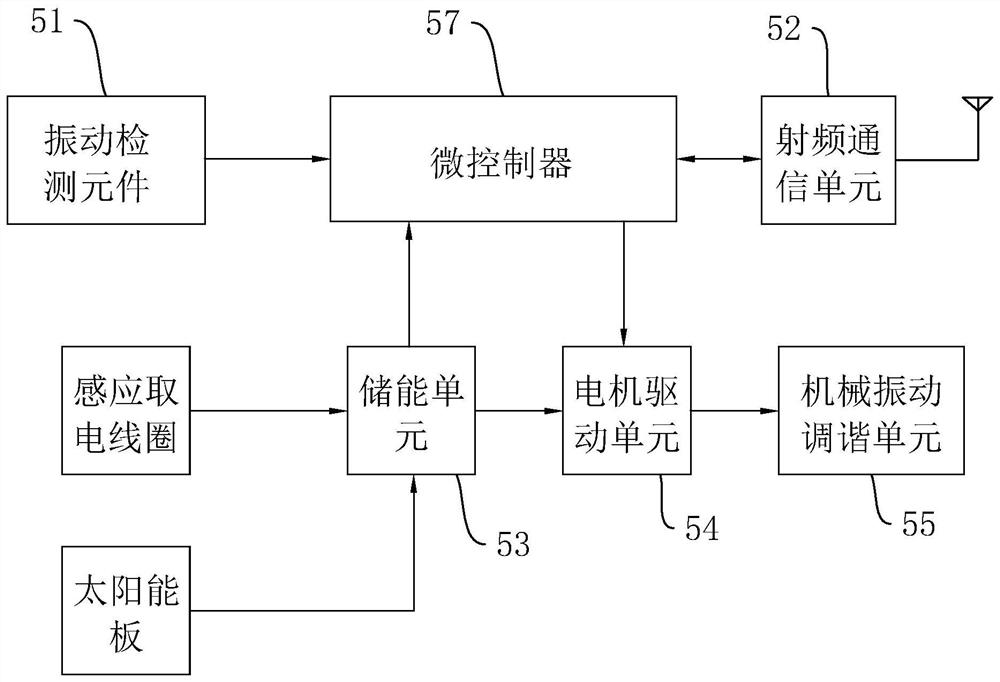
[0033] Embodiment 1 of the present application discloses an intelligent wire anti-vibration hammer, referring to figure 1, including a main control unit for detecting the vibration frequency and amplitude of the wire and outputting a signal, the main control unit includes a vibration detection element 51, the vibration detection element 51 is a vibration sensor, and the vibration sensor is composed of a strain gauge and a strain beam, which is used to detect the Vibration frequency and vibration amplitude. The output end of the vibration detection element 51 is electrically connected with a microcontroller 57, which is an MCU and is used to receive the output signal of the vibration detection element 51 to measure and calculate the vibration frequency and vibration amplitude of the wire. The output end of the microcontroller 57 is electrically connected to the motor drive unit 54 , and the output end of the motor drive unit 54 is electrically connected to the mechanical vibrat...
Embodiment 2
[0044] The second embodiment of the present application discloses an intelligent wire anti-vibration hammer, refer to Image 6 , the difference from the first embodiment is that the two damping elastic rods 3 are in the same vertical plane and are out of phase, the resonance frequency adjustment nut 41 is horizontal, and the screw 42 and the damping elasticity of the resonance frequency adjustment nut 41 connected to the same piece The rod 3 is in the same horizontal plane, the two screws 42 are also in the same vertical plane, the screw gear 43 and the fixed end 22 are in the same horizontal plane, and the resonance frequency adjustment nut 41 through which the damping elastic rod 3 is located at a low position is slidably connected to the same horizontal plane. The inner bottom surface of the shell B 31, the resonance frequency adjusting nut 41 pierced by the damping elastic rod 3 at a high position is slidably connected to the inner top surface of the shell B 31, and the inn...
Embodiment 3
[0047] The third embodiment of the present application discloses an intelligent wire anti-vibration hammer, refer to Figure 7 and Figure 8 , the difference from Embodiment 1 and Embodiment 2 is that the axes of the two damping elastic rods 3 are the same, and the bottom surface of the outer casing B 31 is integrally formed with a vertical bracket 24, the bracket 24 is parallel to the width direction of the outer casing B 31, and the damping elastic rods The fixed ends 22 of 3 are respectively located on two opposite vertical sides of the bracket 24, the resonance frequency adjustment nut 41 is vertical, the resonance frequency adjustment nut 41 is slidably connected to the bottom surface of the shell B 31, and the two screws 42 are respectively connected to the bracket 24. Opposite the two vertical sides, the axes of the two screws 42 are the same, the screws 42 are located just above the damping elastic rod 3, the two screw gears 43 are both close to the bracket 24, the dri...
PUM
 Abstract
Description
Claims
Application Information
 - R&D
- Intellectual Property
- Life Sciences
- Materials
- Tech Scout
- Unparalleled Data Quality
- Higher Quality Content
- 60% Fewer Hallucinations
Browse by: Latest US Patents, China's latest patents, Technical Efficacy Thesaurus, Application Domain, Technology Topic, Popular Technical Reports.
© 2025 PatSnap. All rights reserved.Legal|Privacy policy|Modern Slavery Act Transparency Statement|Sitemap|About US| Contact US: help@patsnap.com