A-E-C three-axis communication-in-motion antenna pedestal

An A-E-C, antenna base technology, applied to antennas, antennas suitable for movable objects, antenna supports/installation devices, etc., can solve the problem of vehicles passing through tunnels, reducing the maximum running speed of the same power carrier, and the wind resistance of the mobile carrier. problems such as becoming larger, to achieve the effect of high overall stiffness

Pending Publication Date: 2021-06-11
NO 54 INST OF CHINA ELECTRONICS SCI & TECH GRP
View PDF0 Cites 0 Cited by
  • Summary
  • Abstract
  • Description
  • Claims
  • Application Information

AI Technical Summary

Problems solved by technology

[0004] If the height of the antenna is too high, the wind resistance of the mobile carrier will increase, the passability of the mobile carrier and the maximum operating speed of the same power carrier will be reduced, and the vehicle will not even be able to pass through the existing tunnel.

Method used


Image

  • A-E-C three-axis communication-in-motion antenna pedestal
  • A-E-C three-axis communication-in-motion antenna pedestal
  • A-E-C three-axis communication-in-motion antenna pedestal

Examples


Embodiment Construction

[0025] Below, the present invention will be further described in conjunction with the accompanying drawings and specific embodiments.

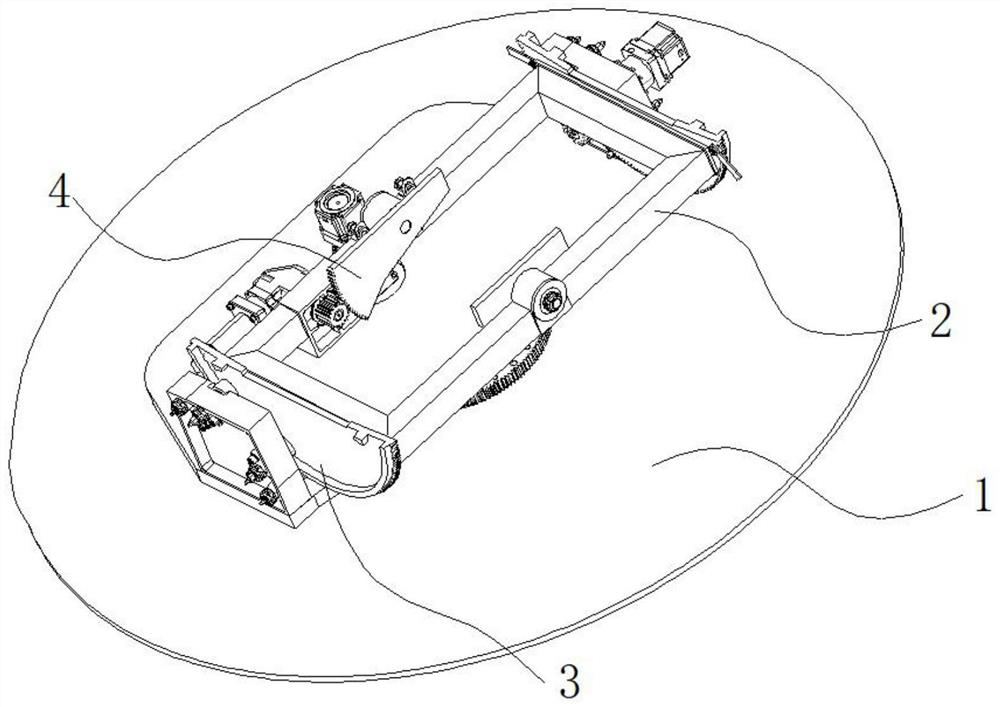
[0026] An A-E-C three-axis moving communication antenna mount, including a chassis 1, an azimuth rotation mechanism, a pitch mechanism and a cross mechanism,

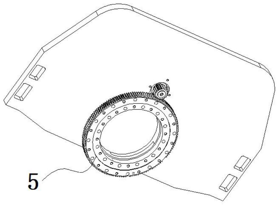
[0027] The azimuth rotation mechanism includes an azimuth gear 5 located on the chassis; the top of the azimuth gear is fixed with a bottom plate;

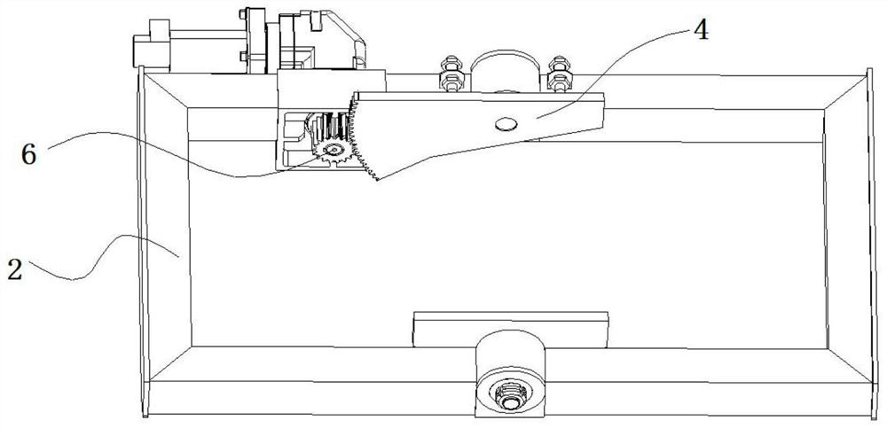
[0028] Described pitching mechanism comprises pitching frame 2, and pitching frame comprises a pair of crossbeam and a pair of longitudinal beam; Pitching fan gear 3 is all provided with two longitudinal beams outside of pitching frame; Pitching gears are respectively arranged on the wall surface of the plate 9; the pitching frame is located between the two support plates, and the pitching fan gear and the pitching gear 8 are meshed;

[0029] The cross mechanism includes a cross gear 6 and two cross sector gears 4; the two cross sector gea...


PUM


Abstract

The invention discloses an A-E-C three-axis communication-in-motion antenna pedestal, and belongs to the technical field of antennas. The A-E-C three-axis communication-in-motion antenna pedestal comprises a chassis, an azimuth rotating mechanism, a pitching mechanism and a crossing mechanism, wherein the azimuth rotating mechanism comprises an azimuth gear positioned on the chassis; a bottom plate is fixedly arranged at the top part of the azimuth gear; the pitching mechanism comprises a pitching frame, and a pitching sector gear perpendicular to the pitching frame is fixedly arranged on the pitching frame; two opposite supporting plates are arranged on the bottom plate, and pitching gears are arranged on the wall faces of the two supporting plates respectively; the pitching frame is located between the two supporting plates, and the pitching sector gear is meshed with the pitching gear; and the crossing mechanism comprises a crossing gear and two crossing sector gears. According to the A-E-C three-axis communication-in-motion antenna pedestal, the loading height of an antenna is reduced, stable and reliable tracking of the antenna in the moving process of the mobile carrier is facilitated, and stability and smoothness of a satellite communication link are ensured.

Description

technical field [0001] The invention relates to the technical field of antennas, in particular to an A-E-C three-axis moving communication antenna mount. Background technique [0002] The three-axis mobile satellite antenna is a satellite communication antenna applied to a mobile carrier. Its main feature is that after the antenna beam points to the satellite during the movement of the carrier, the antenna needs to maintain stable tracking and achieve stable overhead tracking. During the tracking process, the antenna needs to withstand various vibration shocks and wind loads brought by the movement of the mobile carrier, and the pointing of the antenna needs to be kept stable to ensure the smooth flow of the satellite communication link. [0003] For the three-axis mobile satellite antenna mount, reducing the height of the antenna is an important method to reduce the wind resistance of the mobile carrier. The existing three-axis moving satellite antenna mount generally adop...

Claims


Application Information

Patent Timeline
Patent Type & Authority Applications(China)
IPC IPC(8): H01Q1/22H01Q1/27H01Q3/02
CPCH01Q1/22H01Q1/27H01Q3/02
Inventor 尚江华孙庆余宋建虎吴云皓
Owner NO 54 INST OF CHINA ELECTRONICS SCI & TECH GRP
Why Eureka
Try Eureka