
Cooling system device for magnetic axial bearing

An axial bearing and cooling system technology, applied in the direction of bearing cooling, magnetic bearing, shaft and bearing, etc., can solve the problems of increasing friction, reducing system reliability, poor ventilation and heat dissipation conditions, and achieving the effect of uniform heat dissipation

Inactive Publication Date: 2021-06-11
廖加胞
View PDF0 Cites 0 Cited by
  • Summary
  • Abstract
  • Description
  • Claims
  • Application Information

AI Technical Summary

Problems solved by technology

[0003] Magnetic bearings are generally installed in sealed housings, with poor ventilation and heat dissipation conditions. Excessive system temperature will cause thermal expansion of rotor components, generate thermal stress, or change the gap between the magnetic bearing stator and rotor, thereby reducing system reliability.
[0004] At present, most of the existing magnetic bearing cooling adopts medium cooling, which will increase the viscosity of the shaft, thereby increasing friction, and the loss of the medium is large, so it is necessary to develop a non-contact cooling system to overcome the above technical problems

Method used


Image

  • Cooling system device for magnetic axial bearing
  • Cooling system device for magnetic axial bearing
  • Cooling system device for magnetic axial bearing

Examples


Embodiment Construction

[0028] In order to facilitate understanding of the present invention, the present invention will be described more fully described with reference to the related drawings. The preferred embodiment of the present invention is given in the drawings. However, the present invention can be implemented in a variety of different forms, and is not limited to the embodiments described herein. Conversely, the purpose of providing these embodiments is to make a more thorough understanding of the disclosure of the present invention.

[0029] Further, the elements in the present invention are referred to as "fixed to" or "set to" another element, which can be directly in another element or may also exist in the hidden components. When a component is considered to be "connected" another element, it may be directly connected to another element or may always exist in the center element. The term "vertical", "horizontal", "left", "right", "left", "right", "left", "right", and similar expressions ar...


PUM


Abstract

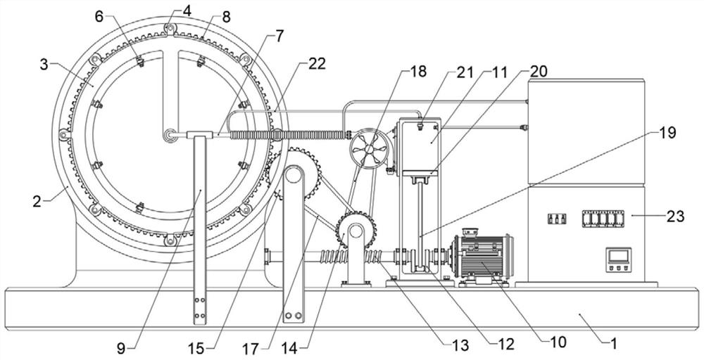
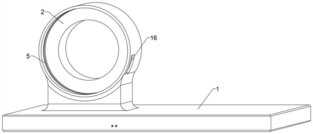
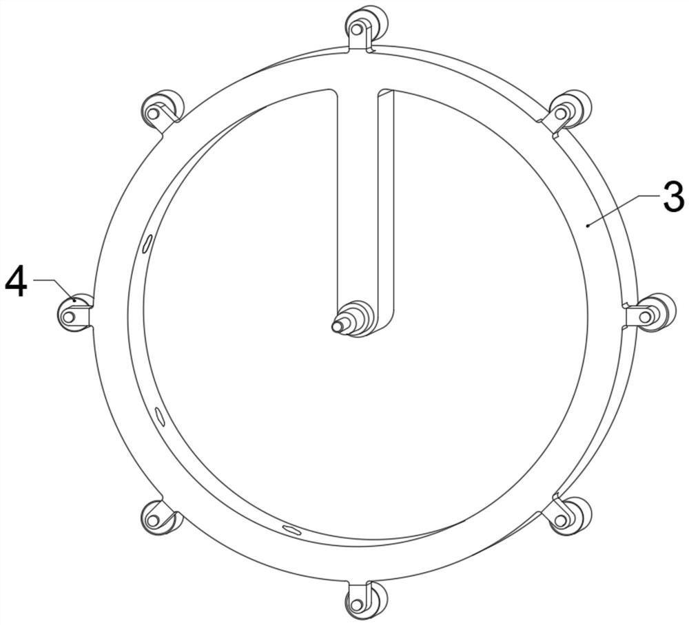
The invention discloses a cooling system device for a magnetic axial bearing. A rotating ring is rotatably arranged in an annular seat, and a plurality of snifting valves for cooling the magnetic bearing are arranged on the rotating ring along the circumference; a rotating mechanism is arranged on a mounting base, an air supply assembly used for pumping air into the rotating ring is further arranged on the mounting base, and a condensation assembly used for cooling the pumped air is attached to the air supply assembly; when a power device works, the air supply assembly and the condensation assembly are driven to work at the same time, wherein the air supply assembly continuously pumps air flow to an extending part of the rotating ring, and the fed air flow is sprayed to the magnetic bearing through the snifting valves distributed circumferentially; the condensation assembly is used for cooling the air flow passing through the air supply assembly, so that the air flow sprayed out of the snifting valves has a low initial temperature, and heat exchange with hot air around the magnetic bearing is achieved; and in addition, the air supply assembly drives a cargo transfer mechanism to act so as to drive the whole rotating ring to rotate.

Description

Technical field [0001] The present invention relates to a mechanical cooling system, specifically a cooling system device for a magnetic axial bearing. Background technique [0002] Magnetic bearings also referred to as electromagnetic bearing or magnetic levitation bearing, which is the utilization of magnetic force to suspend the rotating shaft in a space-specific position, achieving the effect of conventional bearing, which avoids direct contact wear of the rotor and the bearing. [0003] Magnetic bearings are generally mounted in a sealed housing, poor ventilation and heat dissipation conditions, and the system temperature is too high to cause thermal expansion of the rotor member, generate thermal stress or change the gap between the magnetic bearing strats and the rotor, thereby reducing the reliability of the system. [0004] At present, existing magnetic bearing cooling is mostly cooled by medium, and the medium cooling increases the adhesion of the shaft, thereby increas...

Claims


Application Information

Patent Timeline
Patent Type & Authority Applications(China)
IPC IPC(8): F16C37/00F16C32/04
CPCF16C32/0406F16C37/005
Inventor 廖加胞
Owner 廖加胞
Learn More